
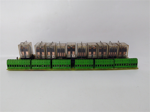
Description
Detailed Technical Parameters
GE DS200UPLAG1B provides 16 digital input channels (24V DC nominal, with 1ms hardware debounce and timestamping capability), 16 digital output channels (solid-state relays rated at 0.5A continuous per channel with 60V DC maximum switching voltage and integrated thermal overload protection), and 8 analog input channels (16-bit resolution, configurable for 0-10V, 4-20mA, or ±10V with ±0.07% accuracy across the full -30°C to +65°C operating range). The board’s distinguishing feature is its power system monitoring capability: 6 dedicated AC voltage input channels (0-600V AC, isolated, with 0.15% accuracy) and 6 dedicated AC current input channels (0-5A or 0-1A, isolated, with 0.15% accuracy), supporting both PT and CT inputs with enhanced input filtering for improved noise rejection. The board incorporates 4 dedicated frequency measurement channels for grid synchronization, measuring 45-65Hz with 0.001Hz resolution. Onboard processing handles synchronization logic, under/over frequency protection (81), voltage protection (27/59), and load sharing calculations, with refined algorithms for improved stability and response. Communication occurs through a proprietary backplane interface at 8MB/s with 10ms cycle time. GE DS200UPLAG1B draws approximately 22W from the +5V DC and ±15V DC backplane rails and features conformal coating conforming to MIL-I-46058C with vibration tolerance rated at 5G (10-500Hz) and shock resistance at 30G. All field connections terminate through three 50-pin D-sub connectors with gold-plated contacts and integral strain-relief brackets.
Advantages & Features
GE DS200UPLAG1B offers several distinctive advantages that differentiate it from the base G1 model and from third-party synchronizer panels. The improved accuracy (0.15% vs. 0.2%) provides more precise power measurements for generator control and grid compliance, enabling tighter voltage and frequency regulation and reducing the risk of nuisance trips due to measurement errors. The enhanced input filtering improves noise rejection in electrically noisy environments, providing more stable readings in industrial settings with variable frequency drives or other power electronics. The “B” revision includes refined firmware with optimized synchronization algorithms and improved protection response characteristics. The integration of power monitoring, synchronization, and protection functions directly into the Mark V chassis eliminates separate synchronizer panels, reducing cabinet footprint and simplifying system architecture. The dedicated AC inputs with isolated CT/PT connections provide accurate generator monitoring for precise control. The onboard frequency measurement with 0.001Hz resolution enables precise grid synchronization. Full integration with Mark V generator control algorithms ensures seamless coordination between turbine governor and grid requirements.
Application Cases & Application Fields
GE DS200UPLAG1B is deployed in power generation facilities requiring precise generator synchronization and grid monitoring. In a 500MW combined-cycle plant, the board provides accurate voltage and frequency measurement for grid synchronization. In an island mode application, it enables load sharing between multiple generators. The board is also used in industrial cogeneration facilities for grid interconnection and compliance monitoring.
Competitor Comparison
Versus the base GE DS200UPLAG1 (0.2% accuracy), the “B” variant provides improved accuracy and refined firmware. Versus the “A” variant, the “B” offers similar accuracy but different firmware optimization characteristics. Versus standard UCI boards, the UPLA provides dedicated AC power monitoring and synchronization capabilities. Versus third-party synchronizer panels, the UPLA integrates seamlessly with Mark V control logic.
Selection Suggestions
Choose GE DS200UPLAG1B for Mark V installations requiring precise generator synchronization with improved accuracy over the base model. This variant offers a balanced feature set for standard grid interconnection applications. Verify PT/CT ratings match field installation. Maintain spares considering 14-18 week lead times.
Critical Precautions
Never ground AC signal shields at the GE DS200UPLAG1B connector—ensure proper PT/CT grounding as specified in GE wiring diagrams. Install external protection for CT circuits to prevent open-circuit conditions. Verify PT/CT ratios in application software match field devices. Perform software isolation before hot-swapping. Calibrate power channels annually using certified reference instruments. Store spares in anti-static bags at 15-35°C and rotate stock every 4 years. Over 40% of field issues trace to improper CT/PT connections or incorrect ratio settings—verify wiring and software configuration before commissioning. Ensure CT circuits are shorted before disconnecting wiring to prevent personnel injury.
A-B 1756-IF16
Alcatel-Lucent OS9-GNI-C24E
BENTLY 106M1079-01
FOXBORO FBM242



Reviews
There are no reviews yet.