
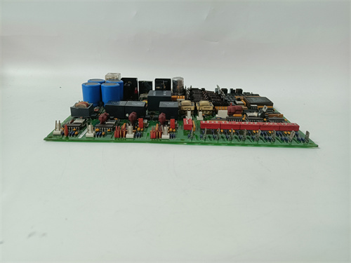
Description
Technical Parameters & Specifications
Manufacturer: General Electric (GE)
Series: Speedtronic Mark V / Mark VIe
Board Type: Thermocouple Input Terminal Board with 2-Wire Configuration
Number of Channels: 16 differential analog input channels
Input Signal Range: -10 mV to +100 mV (typical for thermocouple types J, K, T, E)
Cold Junction Compensation: Single onboard precision temperature sensor for automatic CJ compensation
Isolation: 1500V AC optical isolation between field inputs and logic circuitry
Power Supply: +5V DC and ±15V DC derived from the main backplane (via the DS200TCDAG2B connector)
Resolution: 16-bit analog-to-digital conversion
Accuracy: ±0.12% of full scale (at 25°C ambient)
Sampling Rate: 5 Hz per channel (sequential scanning)
Operating Temperature: -25°C to +60°C
Storage Temperature: -40°C to +85°C
Mounting: Rack-mounted within the VME-based turbine cabinet
Suffix Breakdown: The “G2B” designation on the DS200TCDAG2B indicates:
-
2: Variant with different terminal/pin assignment compared to G1 series (optimized for specific backplane wiring or channel grouping)
-
B: Basic configuration (single cold-junction, open/short diagnostics only, fixed firmware)
Revision Difference from DS200TCDAG1B: The DS200TCDAG2B shares the same electrical specifications, firmware, and basic feature set as the DS200TCDAG1B, but with a different channel-to-terminal mapping. This variant is used when the physical wiring layout in the cabinet requires a specific pinout that differs from the standard G1 arrangement. In some installations, the G2 version provides easier cable management or matches legacy wiring schemes from older turbine upgrades.
Advantages & Key Features
The DS200TCDAG2B stands out due to its specific wiring flexibility combined with proven reliability for legacy turbine installations. Key advantages include:
Specialized Wiring Configuration: The DS200TCDAG2B offers a unique channel-to-terminal mapping that accommodates specific cabinet layouts or retrofit scenarios where the standard G1 pinout does not align with existing field wiring. This eliminates the need for rewiring or adapter cables, significantly reducing installation time and labor costs.
Field-Proven Reliability: Like the DS200TCDAG1B, the DS200TCDAG2B has been deployed in thousands of turbines worldwide since the late 1990s, with a well-documented failure rate of less than 0.5% per year in properly maintained cabinets. Its mature design means most failure modes are well understood and easily troubleshooted.
Basic Self-Diagnostics: Built-in open-circuit and short-circuit detection for each thermocouple channel alerts the control system immediately upon sensor failure. While it lacks the advanced drift detection of the DS200TCDAG1ADA, the DS200TCDAG2B provides adequate protection for standard operational needs.
Simple Replacement Process: Because the DS200TCDAG2B has no field-upgradeable firmware or complex configuration parameters, replacement is straightforward—simply swap the board and verify channel readings. No software reconfiguration is typically required in Mark V systems, making it ideal for quick field replacements.
Cost-Effective for Legacy Systems: For plants running older Mark V cabinets that cannot support the enhanced diagnostics of newer boards, the DS200TCDAG2B offers an economical spare parts solution without unnecessary features that may not be utilized.
LED Status Indicators: 16 individual channel LEDs (green for normal, red for open/short fault) plus a single board health LED for rapid troubleshooting without external tools.
Conformal Coating: All PCBs are coated with a standard acrylic conformal coating to resist moisture, dust, and mild corrosive environments, suitable for most indoor turbine control rooms.
Backward Compatibility: The DS200TCDAG2B is fully compatible with all Mark V cabinets and can also function in Mark VIe backplanes (though without hot-swap capability on older backplane revisions). Its pinout is designed to match specific GE cabinet wiring standards for G2-series boards.
Application Cases in Industrial Fields
This board is predominantly deployed in the power generation, oil & gas, and industrial cogeneration sectors, particularly in installations where the G2 wiring scheme is standard. Specific use cases include:
Legacy Gas Turbine Retrofits: In older Frame 5, 6B, and 7E turbines that underwent control system upgrades, the DS200TCDAG2B is often specified because the existing field wiring was originally terminated for G2-series terminal assignments. Using the DS200TCDAG2B allows a direct drop-in replacement without modifying the terminal blocks or re-pulling thermocouple cables.
Steam Turbine Bearing Temperature Monitoring: In conventional thermal power plants with GE steam turbine controls, the board tracks journal and thrust bearing temperatures. The DS200TCDAG2B is used in cabinets where the wiring harness was manufactured to G2 specifications, ensuring compatibility with the existing cable routing.
Compressor Inlet and Discharge Temperature: In natural gas pipeline compressor stations, the DS200TCDAG2B monitors the inlet and discharge temperatures of centrifugal compressors driven by GE turbines. Certain compressor packages were delivered with G2 wiring as standard, making this board the correct replacement choice.
Industrial Cogeneration Plants: In combined heat and power (CHP) installations, the DS200TCDAG2B is often found in the original equipment manufacturer (OEM) cabinets for specific turbine packages. Plant engineers rely on this board for its plug-and-play compatibility with the existing wiring layout.
Emergency Backup for G2-System Installations: Many plants maintain a stock of DS200TCDAG2B boards specifically as emergency spares for their G2-configured cabinets. Attempting to use a G1 board in a G2 system would require rewiring the terminal blocks, which is impractical during an unplanned outage.
Comparison with Competing Products
| Feature | DS200TCDAG2B (GE) |
Competitor A (e.g., ABB TTH300) | Competitor B (e.g., Siemens 7KG7750) |
|---|---|---|---|
| Channel Count | 16 differential | 8 differential | 12 differential |
| Isolation Voltage | 1500V AC | 1000V AC | 1500V AC |
| Cold Junction Comp. | Single, automatic | Single, configurable | Single, external reference |
| Hot-Swap Support | No (Mark V) / Yes (Mark VIe with backplane rev) | No | Yes (with specific firmware) |
| Diagnostics | Open/short only | Group-level only | Per-channel with HART |
| Firmware Upgradeable | No (fixed firmware) | No | Limited (factory only) |
| Accuracy | ±0.12% | ±0.10% | ±0.12% |
| Wiring Configuration | G2-specific pinout (unique) | Standard | Standard |
| Backward Compatibility with G2 Cabs | Yes (direct fit) | No | No |
| Relative Cost | Lower (mature product) | Higher | Higher |
While competitors offer simultaneous sampling and slightly better accuracy, the DS200TCDAG2B is the only board that provides direct compatibility with GE Mark V cabinets configured for G2 wiring. Its native integration into the VME backplane and specific pinout make it irreplaceable for plants with G2-standard field terminations. For these installations, the DS200TCDAG2B is not just the preferred choice—it is often the only practical choice.
Selection Guidelines & Suggestions
When specifying or replacing a DS200TCDAG2B, consider the following:
Verify Cabinet Wiring Standard: The most critical selection criterion is confirming whether your cabinet uses G1 or G2 wiring. The DS200TCDAG2B has a different channel-to-terminal mapping than the DS200TCDAG1B. Installing the wrong version will cause incorrect thermocouple readings (e.g., Channel 1 may read from the sensor wired to Channel 9). Consult your cabinet wiring diagram or the GE publication that specifies the terminal assignments for your system.
Assess Retrofit Scenarios: If you are replacing a failed board in a G2 cabinet, the DS200TCDAG2B is the correct choice. If you are upgrading the entire cabinet and rewiring is feasible, consider switching to the DS200TCDAG1ADA for enhanced diagnostics—but this requires new terminal blocks and cable re-termination, which may be cost-prohibitive.
Thermocouple Type Compatibility: Confirm that your installed thermocouples are Type J or K. The DS200TCDAG2B hardware linearization is optimized for these two types. Using Type T or E is possible but will reduce accuracy to approximately ±0.25%, which may still be acceptable for non-critical monitoring.
Cable Termination: Use the correct GE-supplied terminal blocks designed for the DS200TCDAG2B (these differ from G1 terminal blocks). Ensure the terminal block part number matches the board. The pinout must align with the G2 standard—using the wrong terminal block will cause miswiring even if the board itself is correct.
Spare Parts Strategy: Given that GE has discontinued new production of the DS200TCDAG2B , only refurbished or surplus units are available. Purchase from reputable suppliers who provide:
-
Full functional testing with a test report
-
Pinout verification to ensure G2 configuration
-
1-year minimum warranty
-
30-day return policy
-
Clear documentation of the board’s revision and tested pin assignments
Documentation Review: Before installation, obtain the GE wiring diagram specific to the DS200TCDAG2B . The terminal pinout is different from the G1 series—mistakenly wiring to G1 terminals on a G2 board will result in scrambled channel readings. Use a multimeter to verify continuity from the thermocouple sensor to the correct terminal pin before powering up.
Consider Upgrade Path: If your plant plans to upgrade to Mark VIe within the next 3–5 years, evaluate whether the new system will continue to support G2 wiring. If the upgrade includes new terminal blocks and cabling, the DS200TCDAG2B may become obsolete. In that case, consider stocking only a minimal number of DS200TCDAG2B boards for the transition period.
Important Precautions
ESD Sensitivity: The DS200TCDAG2B is sensitive to electrostatic discharge. Always wear a grounded wrist strap with a 1MΩ resistor, handle the board by its edges, and place it on an anti-static mat during servicing. Store spare boards in original anti-static bags.
Mandatory Power Down for Mark V: The DS200TCDAG2B does not support hot-swap in Mark V systems. You must de-energize the entire rack before removing or inserting this board. Failure to do so can cause backplane damage, corrupt the main processor’s I/O scan, and potentially trip the turbine. For Mark VIe, hot-swap is supported only if the backplane revision is D or later.
Avoid Over-Torquing Terminals: The screw terminals for thermocouple wiring are rated for 0.5 N·m (4.4 in-lb) maximum. Over-tightening can crack the PCB traces or strip the terminal threads. Use a torque-controlled screwdriver.
Pinout Verification: Because the DS200TCDAG2B uses a non-standard pinout, it is critical to verify that the terminal block wiring matches the board’s channel assignment. Do not assume that a board labeled “TCDAG2B” can be swapped with a “TCDAG1B” without rewiring. Consult the wiring diagram and use a continuity tester before applying power.
Calibration Interval: GE recommends recalibration every 24 months using a precision millivolt source (accuracy ±0.01%) and a certified reference thermometer. The DS200TCDAG2B stores calibration coefficients in EEPROM. If power is interrupted during calibration write cycle, coefficients may be corrupted—ensure stable backplane power throughout the procedure.
Environmental Limits: Do not expose the DS200TCDAG2B to ambient temperatures above 60°C or below -25°C. Maintain cabinet relative humidity between 5% and 95% non-condensing.
Proper Grounding: The DS200TCDAG2B requires a solid, low-impedance earth ground connection through the backplane. Verify that the cabinet ground bus is connected to the plant grounding grid with a resistance of less than 1Ω. Floating grounds can cause erratic readings and intermittent faults.
Disposal Compliance: When decommissioning, follow local WEEE directives. This board contains lead-based solder and flame-retardant materials that require specialized recycling. Do not incinerate or landfill.
Do Not Mix G1 and G2 Boards Without Verification: While the DS200TCDAG2B is electrically compatible with G1 boards, the wiring in the cabinet must be consistent. Mixing G1 and G2 boards in the same rack is possible only if the terminal blocks are correctly matched to each board’s pinout. Label each board slot clearly to prevent future confusion.
Labeling for Future Maintenance: Clearly label the DS200TCDAG2B board and its slot with “G2 CONFIGURATION” to alert future technicians that the wiring differs from standard G1. This simple precaution can prevent costly miswiring errors during later maintenance or emergency replacements.
Final Recommendation
For GE Mark V turbine control systems that were originally built with G2 wiring configuration, the DS200TCDAG2B remains the only drop-in replacement option. Its specific channel-to-terminal mapping matches the existing field wiring, eliminating the need for costly and time-consuming cable re-termination during board replacement. While it lacks the advanced diagnostics of newer boards, its proven reliability, simplicity, and broad availability in the refurbished market make it the practical and cost-effective choice for maintaining legacy G2 systems.
Always source the DS200TCDAG2B from reputable distributors who can verify the G2 pinout configuration through functional testing. Beware of untested “pulls” that may be mislabeled or have damaged connectors—these can lead to incorrect channel readings and potential turbine misoperation.
If you need further assistance with pinout diagrams for the DS200TCDAG2B , step-by-step replacement procedures, or guidance on converting a G2 cabinet to G1 or G1ADA standard, feel free to ask—I can provide detailed wiring comparison tables, re-termination checklists, and verification procedures to ensure a smooth and error-free installation.
HMS AB7000-C
ICS TRIPLEX 9451
WESTINGHOUSE 5X00070G04
DELTA TAU ACC-24E2S DB


Reviews
There are no reviews yet.