
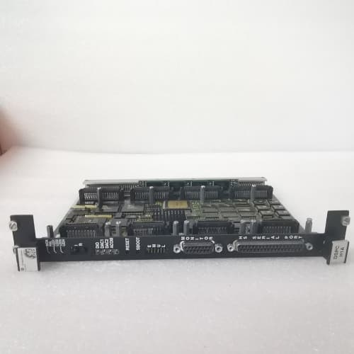
Description
Technical Parameters
Based on the Mark V DS200 series specifications, the DS200TBPXG1A features the following key parameters:
-
Primary Function: Pulse/Frequency Input Termination Board
-
Input Channels: 8 pulse/frequency input channels
-
Signal Types Supported: Magnetic pickup sensors, proximity probes (eddy current), encoders (TTL/HTL), flowmeter pulses, speed sensors
-
Input Voltage Range: 0-24V DC (configurable threshold)
-
Frequency Range: 0-20kHz per channel (typical)
-
Input Impedance: >10 kΩ
-
Terminal Type: Screw-type terminal blocks (accepts 0.5-2.5mm² wire, AWG 20-14)
-
Voltage Rating: 300V AC/DC maximum
-
Current Rating: 10A per terminal (maximum)
-
Isolation: No active isolation (passive termination); relies on connected modules for isolation
-
Form Factor: Single-slot 6U Eurocard (160mm), 96-pin DIN connector to backplane
-
Mounting: Direct plug-in to Mark V rack; front-facing screw terminals for field wiring
-
Operating Environment: 0°C to 60°C ambient temperature, 5% to 95% non-condensing humidity
-
Labels: Clearly marked channel designations with type selection guides
-
Compliance: UL recognized, CE marked
Advantages and Features
The DS200TBPXG1A offers several distinctive advantages for Mark V system pulse signal termination:
-
High-Speed Pulse Input Support: The DS200TBPXG1A handles frequencies up to 20kHz, making it suitable for speed sensors, flowmeters, and encoder applications in turbine control systems.
-
Multi-Sensor Compatibility: Accepts signals from magnetic pickups, proximity probes, encoders, and flowmeters, providing flexibility for various pulse-based measurement applications.
-
High-Density Termination: With 8 channels, the DS200TBPXG1A provides efficient termination for multiple pulse sensors in a single slot.
-
Screw-Type Terminals: Uses reliable screw-type connections that accommodate 0.5-2.5mm² wire, ensuring secure, long-term field connections.
-
Passive Design: Contains no active electronics, making the DS200TBPXG1A highly reliable and immune to electronic failures.
-
Direct Rack Integration: Plugs directly into the Mark V backplane, providing a clean interface.
-
Hot-Swap Capable: Supports live insertion and removal with proper ESD protocols.
-
Clear Labeling: Each channel is clearly marked, reducing wiring errors.
Application Cases in Application Fields
The DS200TBPXG1A is deployed across multiple heavy-industrial sectors:
-
Combined Cycle Power Plants: A 750MW CCPP facility uses the DS200TBPXG1A to terminate speed sensors (magnetic pickups) on gas and steam turbines for accurate speed monitoring and overspeed protection.
-
Steam Turbine Retrofits: During a control system refurbishment, a facility installed the DS200TBPXG1A for speed sensor termination, ensuring precise frequency measurement for turbine speed control.
-
Gas Pipeline Compressor Stations: The DS200TBPXG1A terminates flowmeter pulse signals and speed sensor inputs for compressor performance monitoring and surge protection.
-
Hydroelectric Plants: The DS200TBPXG1A terminates speed sensors and flowmeter signals for turbine speed and flow measurement applications.
Comparison with Competing Products
| Aspect | DS200TBPXG1A | General-Purpose Termination Board | Third-Party Pulse Board |
|---|---|---|---|
| Pulse/Frequency Support | Yes (up to 20kHz) | No | Varies |
| Sensor Compatibility | Magnetic, proximity, encoder, flowmeter | N/A | Varies |
| Channel Count | 8 channels | 16 channels (mixed) | Varies; often 4-8 channels |
| Frequency Range | 0-20kHz | N/A | Varies |
| Terminal Type | Screw-type | Screw-type | Varies |
| Rack Integration | Direct plug-in | Direct plug-in | Requires external mounting |
| Hot-Swap Capable | Yes | Yes | Usually no |
| Passive Design | Yes | Yes | Varies |
Selection Suggestions and Precautions
Before purchasing or installing the DS200TBPXG1A:
-
Verify Exact Model: Ensure the board is precisely DS200TBPXG1A, not DS200TBPXG1B or other variants. Different suffixes may have different channel configurations or frequency ranges.
-
Confirm Sensor Compatibility: Ensure your sensors (magnetic pickup, proximity probe, encoder, flowmeter) match the DS200TBPXG1A input specifications.
-
Frequency Range: Verify that your pulse signals fall within the 0-20kHz range supported by the DS200TBPXG1A.
-
Voltage Levels: Confirm that the sensor output voltage levels are compatible with the DS200TBPXG1A input threshold configuration.
-
Shielding: Use shielded twisted-pair cables for pulse signal wiring. Pulse signals are sensitive to electrical noise; proper shielding is essential. Connect the shield at the DS200TBPXG1A end only.
-
ESD Protection: Use grounded wrist straps during handling.
-
Post-Installation Validation:
-
Verify all terminations are mechanically secure.
-
Confirm correct polarity and wiring for each pulse sensor.
-
Use a signal generator or known pulse source to verify each channel.
-
Verify frequency readings at the HMI match expected values.
-
-
Spare Strategy: Maintain at least one spare DS200TBPXG1A on-site.
-
Supplier Qualification: Request visual inspection and functional testing of pulse input channels before shipment.
Final Recommendation
For GE Mark V turbine systems requiring pulse and frequency signal termination for speed sensors, flowmeters, or encoder applications, the DS200TBPXG1A is the essential solution. Its 8-channel capacity, up to 20kHz frequency support, multi-sensor compatibility, and robust screw-terminals provide accurate, reliable pulse signal routing. Prioritize reputable aftermarket suppliers offering tested units. Maintain spares on-site, use proper shielding practices, and ensure correct wiring to guarantee the long-term reliability of your DS200TBPXG1A and the entire Mark V control system.
YAMAHA TS2620N654E122
SCHNEIDER 140CPU11303
ABB V18345-1010221001
A-B 2094-EN02D-M01-S1



Reviews
There are no reviews yet.