
")
Description
Product Description
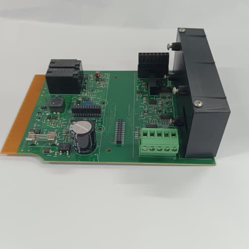
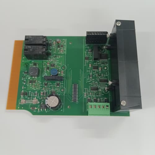
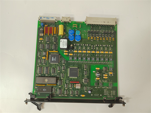
The ALSTOM I/OBE2 12004-104-00 V1.0.0 is a critical I/O (Input/Output) communication module within Alstom’s (now GE Vernova) energy automation and protection systems, specifically designed for use with their IEDs (Intelligent Electronic Devices) like the Px4x series of protection relays or similar bay controllers. The designation I/OBE2 identifies this as a specific I/O Bus Extender or Binary Input/Output module, forming part of a distributed I/O architecture for substation automation. This module, in its specific hardware version 12004-104-00 with firmware V1.0.0, is responsible for gathering discrete status signals from the switchyard (e.g., circuit breaker position, isolator status) and executing control commands (e.g., open/close commands) from the central relay.
Product Parameters
-
Model: ALSTOM I/OBE2 12004-104-00.
-
Firmware/Version: V1.0.0.
-
Function: Binary I/O Communication Module for Protection Relays.
-
I/O Type: Provides a mix of digital inputs (for status monitoring) and digital outputs (relay commands).
-
Number of Channels: Contains a defined number of optically isolated input channels and relay output contacts.
-
Input Voltage Rating: Inputs are rated for high voltage levels typical in substations (e.g., 110V DC, 125V DC, 220V DC) to directly interface with switchgear auxiliary contacts.
-
Output Contact Rating: Relay outputs are rated for commanding circuit breaker trip/close coils or other auxiliary relays (e.g., 30A inrush, 250V AC/DC).
-
Communication Interface: Connects to the main protection relay or controller via a proprietary high-integrity serial bus or optical link.
-
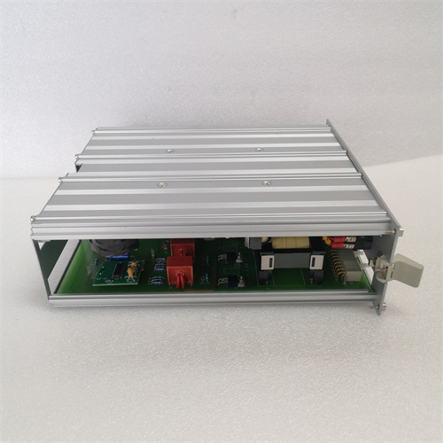
Power Supply: Requires a separate, highly reliable DC power source, typically the station battery.
-
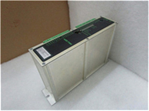
Diagnostics: Features self-diagnostics and status reporting back to the host device.
Advantages and Features
-
High Reliability and Availability: Designed for the critical environment of a substation, with components and design principles ensuring continuous operation and immediate response to commands.
-
Enhanced Electrical Isolation: Provides high-voltage isolation between the harsh switchyard environment and the sensitive electronics of the protection relay, protecting the relay from transients and surges.
-
Deterministic Communication: Utilizes a deterministic communication protocol with the host relay, ensuring fast and predictable transfer of status changes and execution of commands, which is vital for protection sequences.
-
Simplified Wiring and Marshalling: Acts as a remote I/O node, reducing the amount of control cable needed to run from the switchyard to the control room by marshalling signals locally.
-
Firmware-Enabled Flexibility: The V1.0.0 firmware defines the module’s behavior, communication parameters, and potentially configurable I/O functions, allowing for customization within its design scope.
Application Cases in Relevant Fields
-
Circuit Breaker Control and Monitoring in Substations: The primary application of the ALSTOM I/OBE2 12004-104-00 V1.0.0 is to provide the interface for a protection relay to read the breaker’s auxiliary contacts (52a, 52b) and to energize the trip and close coils for remote operation.
-
Disconnector (Isolator) and Earth Switch Monitoring: Used to monitor the open/close/earth position of isolators and grounding switches in a switchyard, providing crucial interlocking data.
-
Distributed I/O for Bay Control Units: In a digital substation, multiple I/OBE2 modules can be distributed around the switchyard, connected to a central bay controller or protection relay via a serial or network link, creating a clean, modular architecture.
-
Alarm and Status Collection: Gathers alarm contacts from various equipment like transformer tap changers, SF6 gas density monitors, and pump/fan statuses for centralized annunciation.
Comparisons with Competing Products
Compared to using individual electromechanical relays and terminal blocks for interfacing, or generic remote I/O modules from PLC manufacturers, the ALSTOM I/OBE2 12004-104-00 is a system-integrated, protection-grade solution.
-
Protection System Integration: It is designed and tested to work seamlessly with specific Alstom/GE protection relays (e.g., Px4x). Its communication protocol, timing, and fail-safe behavior are an integral part of the certified protection system, unlike a generic I/O module.
-
High-Voltage Interface Capability: It is specifically built to handle the voltage levels and electrical noise of a high-voltage switchyard directly, whereas a standard industrial I/O module would require extensive additional interfacing and protection.
-
Support and Interoperability: The module’s behavior with firmware V1.0.0 is guaranteed by the OEM. Using a third-party interface risks communication errors and voids the relay’s type testing and certification for critical protection functions. For guaranteed interoperability and safety, the authentic ALSTOM I/OBE2 12004-104-00 V1.0.0 is the mandated choice.
Selection Suggestions and Precautions
-
Confirm Host Relay Compatibility: This is the most critical step. Verify that the ALSTOM I/OBE2 12004-104-00 module with firmware V1.0.0 is explicitly listed as compatible with your specific protection relay model and its firmware version.
-
Verify I/O Count and Ratings: Ensure the module has enough inputs and outputs for your application and that the voltage ratings (e.g., 125V DC) match your station battery and switchgear auxiliary contact voltage.
-
Source from Authorized Protection Specialists: Purchase exclusively from GE Grid Solutions (GE Vernova) authorized distributors or certified power system integrators. Counterfeit or uncertified I/O modules in protection circuits are an extreme safety hazard.
-
Plan for Firmware Management: Inquire if the firmware V1.0.0 is the latest or required version. Firmware updates, if needed, must be performed using the correct OEM tools and procedures.
-
Implement Robust Power Supply and Wiring: Provide a clean, dedicated power supply from the station battery. Use appropriately sized cables for output commands (trip/close) to handle inrush currents. Follow strict segregation and grounding practices for control cables.
-
Perform Comprehensive Functional Testing: After installation, test every input by operating the primary device (e.g., racking the breaker) and test every output using the relay’s test functionality to verify the ALSTOM I/OBE2 module responds correctly. Document all tests.
1756-IB16DAB PLC
1756-IB16I AB
1756-IB16K AB
1756-IB32 AB
1756-IC16 AB
1756-IF16 AB
.jpg)
Reviews
There are no reviews yet.