
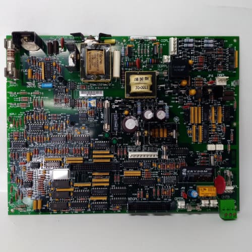
Description
Technical Parameters
-
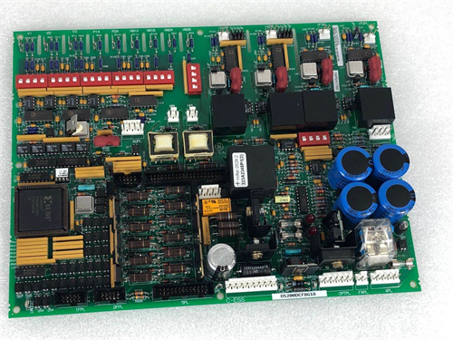
Product Type: Load cell / current conditioner interface board
-
Input channels: 4 differential analog inputs
-
Input types: Strain gauge (bridge), load cell, current transducer (0–20mA, 4–20mA)
-
Excitation voltage: 5 VDC or 10 VDC (selectable)
-
Input sensitivity: 0–10 mV, 0–20 mV, 0–100 mV (selectable via jumpers)
-
Bridge impedance: 350Ω minimum (typical)
-
Signal conditioning: Precision scaling, offset, and filtering
-
Filtering: Enhanced (ADM1 – low-pass filter on all channels)
-
Resolution: 16-bit ADC per channel
-
Accuracy: ±0.05% of full scale
-
Diagnostics: Signal presence detection, enhanced fault detection (ADM1 specific)
-
Terminal type: Spring-clamp (24–16 AWG)
-
Isolation: 2500 Vrms between transducer inputs and drive logic
-
Conformal coating: Marine-grade (moisture and corrosion resistant) – ADM1 specific
-
Mounting: 4× M6 holes (standard GE rack footprint)
-
Operating temperature: -20°C to 70°C (extended)
-
LED indicators: Power, Fault, and per-channel signal presence
Advantages & Features
-
Multi-range inputs – Configurable for different load cell/current transducer sensitivities on GE 531X306LCCADM1 via jumpers (0–10mV, 20mV, 100mV)
-
Spring-clamp terminals – Faster wiring on GE 531X306LCCADM1 reduces installation time
-
Selectable excitation – 5V or 10V excitation on GE 531X306LCCADM1 supports a wide range of bridge transducers
-
Enhanced filtering – Low-pass filters on all channels on GE 531X306LCCADM1 reduce noise for stable tension/current control
-
Enhanced diagnostic monitoring – Signal presence and fault detection on GE 531X306LCCADM1 enables faster troubleshooting
-
High accuracy – ±0.05% for precision tension and current applications
-
Galvanic isolation – 2500 Vrms protects regulator board from transducer faults
-
Marine-grade conformal coating – Protects GE 531X306LCCADM1 from humidity, salt spray, and corrosive gases
-
Extended temperature range – -20°C to 70°C for harsh environments
-
Drop-in replacement – Direct replacement for earlier LCC revisions
Application Cases
-
Large-scale retrofit – System integrator used spring-clamp terminals on GE 531X306LCCADM1 for 15 load cell connections, reducing installation time by 30%
-
Web tension control – Printing press used GE 531X306LCCADM1 with load cells for tension feedback; high accuracy ensured consistent print quality
-
Offshore platform – Corrosive environment used GE 531X306LCCADM1 with load cells for winch tension monitoring; conformal coating prevented salt spray damage
Competitive Comparison
| Aspect | GE 531X306LCCADM1 (OEM) | Generic Aftermarket Load Cell Board |
|---|---|---|
| Input sensitivity | 0–10mV, 20mV, 100mV | Fixed range |
| Auxiliary terminals | Spring-clamp (fast) | Screw or none |
| Excitation voltage | 5V / 10V selectable | Fixed (usually 10V) |
| Diagnostic monitoring | Enhanced (fault detection) | Basic or none |
| Accuracy | ±0.05% | ±0.2–0.5% typical |
| Conformal coating | Marine-grade | None |
| Temperature range | -20°C to 70°C | 0°C to 50°C typical |
Selection Suggestions
-
Choose GE 531X306LCCADM1 for precision tension/current control applications requiring fast wiring, enhanced diagnostics, and harsh environment protection
-
Verify your transducer type (load cell, current transducer) and output sensitivity – configure via jumpers on GE 531X306LCCADM1
-
Verify excitation voltage requirement (5V or 10V) – set via jumpers
-
For current transducers, verify signal type (0–20mA or 4–20mA) – configure via jumpers on GE 531X306LCCADM1
-
Verify field wiring is within 24–16 AWG range for spring-clamp terminals
-
Confirm regulator board compatibility – works with 531X111, 531X139, and 531X305 series
-
For long cable runs (>30m), use shielded twisted-pair cables
-
Prefer remanufactured units with new signal conditioning ICs, capacitors, terminals tested, and coating intact
Precautions
-
Always disconnect power before handling GE 531X306LCCADM1 – transducer wiring may carry excitation voltage
-
For stranded wires on spring-clamp terminals, use ferrules to prevent strand fraying
-
Insert wires fully until the wire stop is reached – partially inserted wires cause intermittent connections
-
Use shielded twisted-pair cables for load cell and current signals – unshielded cables pick up EMI from VFD output
-
For 6-wire load cells (sense + excitation), connect sense wires correctly to compensate for cable resistance
-
Ensure bridge impedance is at least 350Ω – lower impedance may overload the excitation supply on GE 531X306LCCADM1
-
For current transducers, ensure the internal resistor is selected via jumpers on GE 531X306LCCADM1
-
Keep signal cables separated from motor power leads (minimum 30 cm) to avoid EMI-induced errors
-
Inspect conformal coating for scratches or cracks before installation – damaged coating exposes the PCB to corrosion
-
If a channel’s signal presence LED is off, check transducer wiring and excitation voltage first
-
Calibrate the board with known loads/currents after installation to verify scaling on GE 531X306LCCADM1
-
Store spare boards in ESD-safe packaging
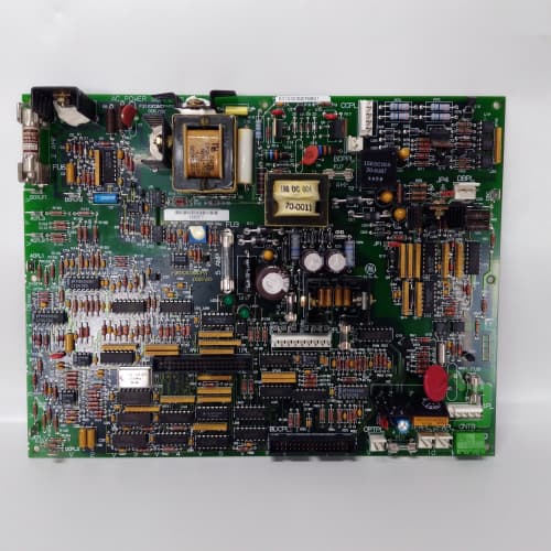
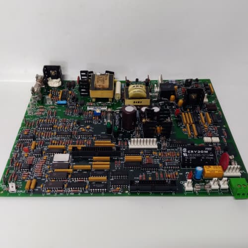
ABB AO801
A-B 1769-SDN
Schneider 140XBP01000


Reviews
There are no reviews yet.