
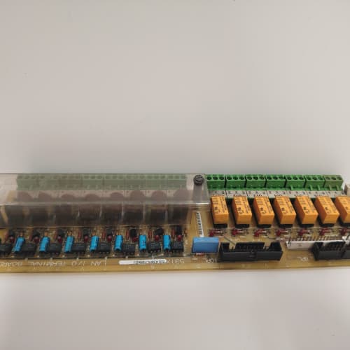
Description
Technical Parameters
-
Product Type: Safety / stop interface board
-
Safety inputs: 1 channel (single – for E-stop or enable circuit) – 24 VDC
-
Safety outputs: 1 relay contact (Form A, 2A @ 30 VDC / 250 VAC)
-
Safety rating: Category 1 / PL c (EN ISO 13849-1) – single-channel architecture
-
Response time: <30 ms (input to output)
-
Diagnostics: Basic – LED indication only (no contact monitoring feedback)
-
Input voltage: 24 VDC (from external safety relay or PLC)
-
Output rating: 2A (resistive) / 0.5A (inductive)
-
Terminal type: Screw-type – 24–12 AWG
-
Isolation: 2500 Vrms between safety circuits and drive logic
-
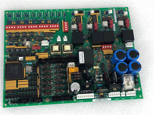
Connectors: One 26-pin header to regulator board; one 10-position terminal block for field wiring
-
Mounting: 4× M4 holes (standard GE rack footprint)
-
Power supply: +5 VDC and +15 VDC from regulator board (for diagnostics/logic)
-
Operating temperature: 0°C to 50°C (standard range)
-
LED indicators: Power, Channel, Fault
Advantages & Features
-
Simple safety interface – Single-channel design on GE 531X175SSBABM1 provides a cost-effective solution for basic safety stop applications
-
Fast response time – <30 ms ensures rapid shutdown in emergency situations
-
Basic diagnostic LEDs – Power, Channel, and Fault indicators on GE 531X175SSBABM1 for simple troubleshooting
-
Galvanic isolation – 2500 Vrms protects regulator board from safety circuit transients
-
Cost-effective – Lower cost than dual-channel versions (AAM3) for non-critical applications
-
Plug-and-play – Pin-compatible with SSB AAM3 and other SSB revisions; no configuration changes needed
Application Cases
-
Basic E-stop integration – Packaging machine used GE 531X175SSBABM1 to interface a single E-stop pushbutton to an AC-300 drive; simple and cost-effective solution for basic safety
-
Enable circuit monitoring – Conveyor system used GE 531X175SSBABM1 to monitor an enable switch (operator presence) on a DC-300 drive, stopping the drive when the switch was released
-
Retrofit – Replaced a failed SSB board in a general-purpose drive with GE 531X175SSBABM1; restored basic safety functionality without requiring parameter changes
Competitive Comparison
| Aspect | GE 531X175SSBABM1 (OEM) | Generic Aftermarket Safety Board |
|---|---|---|
| Safety rating | Category 1 / PL c (single-channel) | Category 1 or lower typical |
| Relay contacts | 1 (2A) | 1 (1A typical) |
| Contact monitoring | None (basic LED only) | Rarely available |
| Response time | <30 ms | 50–100 ms typical |
| Temperature range | 0°C to 50°C | 0°C to 50°C typical |
| Diagnostics | Power, Channel, Fault LEDs | Limited or none |
| Isolation | 2500 Vrms | 1500 Vrms typical |
| Cost | Lower (non-redundant) | Variable |
Selection Suggestions
-
Choose GE 531X175SSBABM1 for non-critical applications where Category 1 / PL c safety rating is sufficient (e.g., basic E-stop, enable circuits)
-
Select ABM1 over AAM3 (dual-channel) for cost-sensitive projects or where redundant safety is not required by risk assessment
-
Verify your safety circuit requirements – GE 531X175SSBABM1 is single-channel and does not meet Category 3 requirements
-
Confirm regulator board compatibility – works with 531X111, 531X139, and 531X305 series
-
Ensure the external safety relay or PLC provides 24 VDC outputs compatible with GE 531X175SSBABM1
-
Prefer remanufactured units with new relay assemblies (mechanical wear is common) and verified contact resistance
Precautions
-
Always disconnect power before handling GE 531X175SSBABM1 – safety circuits may carry 24 VDC from external sources even when the drive is off
-
Do not exceed 2A on relay contacts – higher current welds the contacts and permanently damages the board
-
Inductive loads (contactors, solenoids) require external flyback diodes (DC) or snubbers (AC) across the coil
-
Relay contacts are normally-open only – for normally-closed safety contacts, use an external safety relay
-
GE 531X175SSBABM1 is single-channel and does not include contact monitoring (feedback loop) – external monitoring may be required for higher safety levels
-
When replacing, verify that all safety wiring (E-stop, enable) is correctly transferred to the new GE 531X175SSBABM1
-
Test the safety function after installation – simulate an E-stop and verify that drive torque is removed within the specified <30 ms
-
Do not bypass safety relays or use the board for non-safety functions – GE 531X175SSBABM1 is designed specifically for safety circuits
-
Torque terminal screws to 0.5–0.6 N·m – over-tightening strips threads; under-tightening causes loose connections and intermittent safety faults
-
If the “Fault” LED illuminates, check the input voltage and relay contacts – the board provides basic indication only
-
Safety circuits must be regularly tested per local regulations – GE 531X175SSBABM1 assists but does not include automatic testing
-
For applications requiring Category 3 / PL d or higher, use the dual-channel GE 531X175SSBAAM3 instead of ABM1 – ABM1 is not suitable for safety-critical functions
-
Store spare boards in ESD-safe packaging – the relay and logic ICs are sensitive to electrostatic discharge
SUPCON XP369B
ETHERWAN EL100T
MITSUBISHI FX3U-32MR/DS


Reviews
There are no reviews yet.