
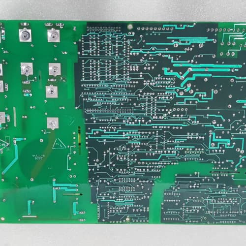
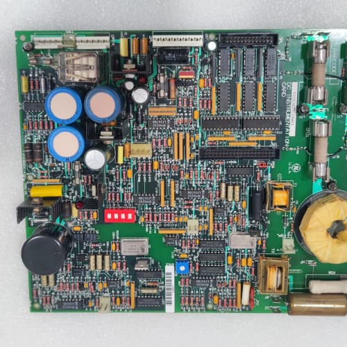
Description
Technical Parameters
-
Product Type: Temperature monitoring terminal board
-
Temperature input channels: 8 differential (universal – thermocouple or RTD)
-
Sensor types: Thermocouple (J, K, T, E) or RTD (Pt100 / Pt1000) – selectable via jumpers
-
Cold-junction compensation: Onboard per-channel (dedicated compensation sensor)
-
RTD excitation: Constant current source (software-selectable)
-
Input impedance: >10 MΩ (thermocouple mode)
-
Accuracy: ±0.1% of full scale
-
Isolation: 1500 Vrms between sensor inputs and drive logic
-
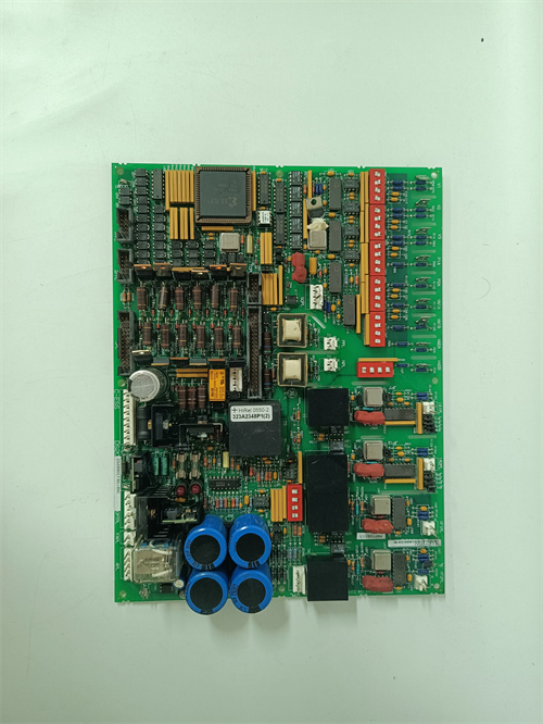
Connectors: One 26-pin header to regulator board (or to 531X155TXM board); two 12-position terminal blocks
-
Terminal type: Screw-type (removable) – 24–12 AWG
-
Mounting: 4× M4 holes (standard GE rack footprint)
-
Power supply: +5 VDC and +15 VDC from regulator board (or pass-through from 531X155TXM)
-
LED indicators: Power and Fault (per channel)
-
Operating temperature: 0°C to 60°C
Advantages & Features
-
Universal sensor inputs – Each channel on GE 531X171TMAABG1 accepts J/K/T/E thermocouples or Pt100/Pt1000 RTDs (jumper-selectable), eliminating the need for multiple terminal board types
-
Per-channel cold-junction compensation – Dedicated compensation sensors on GE 531X171TMAABG1 ensure accurate temperature readings regardless of ambient temperature changes
-
Direct RTD excitation – Constant current source for RTDs eliminates external excitation modules
-
Screw-type removable terminals – Allows field wiring to remain intact while the board is replaced
-
Galvanic isolation – 1500 Vrms protects the regulator board from sensor faults and ground loops
-
Plug-and-play – Direct replacement for earlier TMA revisions; compatible with 531X155TXM series boards
Application Cases
-
Motor bearing monitoring – Paper mill used GE 531X171TMAABG1 to connect 8 Pt100 RTDs to a 531X155TXM temperature board; accurate readings prevented bearing overheating failures
-
Transformer winding monitoring – Wind turbine converter used GE 531X171TMAABG1 with K-type thermocouples to monitor transformer winding temperature, sending warnings to SCADA
-
Multiple temperature points – HVAC chiller plant used GE 531X171TMAABG1 for 8 thermocouples (compressor, condenser, evaporator, and bearing points) with per-channel CJC ensuring accuracy
Competitive Comparison
| Aspect | GE 531X171TMAABG1 (OEM) | Generic Replacement Temperature Terminal Board |
|---|---|---|
| Sensor types | J/K/T/E + Pt100/Pt1000 | Usually one type only |
| CJC per channel | Yes (dedicated compensation) | None or per-board only |
| RTD excitation | Onboard constant current | Requires external module |
| Terminal type | Screw (removable, 24–12 AWG) | Fixed or limited range |
| Isolation | 1500 Vrms | Usually non-isolated |
| Compatibility | Designed for 531X155TXM | May not be compatible |
Selection Suggestions
-
Verify your sensor type (thermocouple vs. RTD) and type (J/K/T/E or Pt100/Pt1000) – GE 531X171TMAABG1 supports all but requires correct jumper settings per channel
-
Confirm regulator board compatibility – works with 531X111, 531X139, and 531X305 series, typically connected via a 531X155TXM temperature interface board
-
For RTD applications, verify 3-wire or 4-wire configuration – GE 531X171TMAABG1 supports both with appropriate termination
-
Prefer remanufactured units with new cold-junction sensors and terminal blocks tested for continuity
Precautions
-
Always disconnect power before handling GE 531X171TMAABG1 – sensor wiring may carry external voltages
-
Use thermocouple extension wire (not copper) from sensor to board – copper wire introduces measurement errors
-
For RTDs, use 3-wire or 4-wire configuration – 2-wire connections introduce significant measurement errors due to lead resistance
-
When replacing, transfer all channel jumper settings (sensor type) to the new GE 531X171TMAABG1 – incorrect settings cause inaccurate readings
-
Keep sensor wiring away from power cables (IGBT, motor leads) to avoid EMI-induced false readings
-
Torque terminal screws to 0.5–0.6 N·m – over-tightening strips threads; under-tightening causes loose connections
-
For shielded cables, ground the shield at the sensor end only (or at the board – follow drive manual recommendations)
-
The per-channel CJC sensors are sensitive to airflow – do not mount GE 531X171TMAABG1 directly in the path of cooling fans, as rapid ambient changes may affect accuracy
-
If a channel reads erratic, check shield grounding and sensor polarity – reversed thermocouple wiring gives negative readings
-
For long cable runs (>30m), use thicker gauge wire (lower resistance) to reduce error – GE 531X171TMAABG1 accepts 24–12 AWG
A-B 440R-C23017
HONEYWELL MC-TDIY22
6ES7322-1BL00-0AA0


Reviews
There are no reviews yet.