
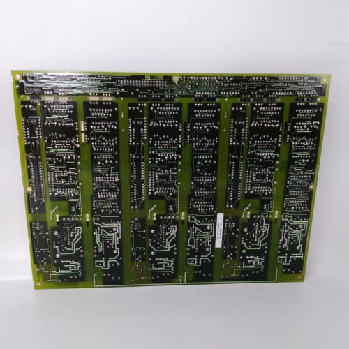
Description
Technical Parameters
-
Product Type: Terminal board / field wiring termination assembly (screw‑type unified)
-
Digital I/O terminals: 32 points (screw‑type only)
-
Analog I/O terminals: 12 points (voltage/current) – with built‑in 24 VDC loop power supply (4–20 mA transmitter excitation)
-
Communication terminals: 6 points (RS‑485, RS‑232) – with EMI filtering and ESD protection
-
Auxiliary power terminals: 6 points (120 VAC / 24 VDC) – screw‑type only
-
Terminal type: Screw‑type (unified across all points) – high‑retention design
-
Wire size: 0.2 – 2.5 mm² (24–12 AWG)
-
Analog loop power supply: 24 VDC / 100 mA (isolated) – onboard
-
Current rating: 10 A per terminal (maximum)
-
Voltage rating: 300 VAC / 600 VAC (terminal‑to‑terminal)
-
EMC filtering: Built‑in ferrite beads and capacitors on communication terminals
-
Surge protection: TVS diodes on analog and communication terminals (±2 kV)
-
Conformal coating: Marine‑grade (moisture and corrosion resistant) – ADS1 specific
-
Connectors: Two 34‑pin headers to regulator board; one 26‑pin header to auxiliary boards
-
Mounting: 4× M4 holes (standard GE rack footprint)
-
Operating temperature: -20°C to 70°C (extended)
Advantages & Features
-
Unified screw‑type terminals – All terminals on GE 531X170TBSADS1 are screw‑type, simplifying spare parts management (one terminal type for all connections) and providing consistent high‑retention performance
-
Marine‑grade conformal coating – Protects GE 531X170TBSADS1 from humidity, salt spray, and corrosive gases, making it suitable for offshore, marine, and chemical plant environments
-
Integrated analog loop power – Onboard 24 VDC isolated supply for 4–20 mA transmitters eliminates external power supplies
-
Enhanced EMC filtering – Built‑in ferrite beads and capacitors on communication terminals protect against EMI and reduce emissions
-
Extended temperature range – -20°C to 70°C for harsh environments
-
Unified wiring – All connections use screw terminals (24–12 AWG), reducing confusion between terminal types
-
Plug‑and‑play – Direct replacement for earlier TBS revisions; no configuration changes needed
Application Cases
-
Offshore drilling platform – AC‑300 drive exposed to salt spray used GE 531X170TBSADS1; the marine‑grade conformal coating prevented corrosion and terminal degradation after 3 years of continuous operation
-
Chemical processing plant – Corrosive atmosphere (chlorine gas) destroyed standard terminal boards within months; GE 531X170TBSADS1 with conformal coating survived without failure
-
4–20 mA transmitter integration – Wastewater treatment plant connected pressure and flow transmitters directly to GE 531X170TBSADS1; onboard loop power eliminated external power supplies and simplified wiring
Competitive Comparison
| Aspect | GE 531X170TBSADS1 (OEM) | Generic Replacement Terminal Board |
|---|---|---|
| Terminal type | Unified screw (all points) | Mixed or single type |
| Conformal coating | Marine‑grade (moisture/corrosion) | None or basic (limited) |
| Analog loop power | Onboard 24V / 100 mA isolated | None |
| Temperature range | -20°C to 70°C | 0°C to 50°C typical |
| EMC filtering | Ferrite + capacitors (comms) | None |
| Corrosion resistance | High (salt spray, chemicals) | Low to moderate |
Selection Suggestions
-
Choose GE 531X170TBSADS1 for offshore, marine, chemical, or high‑humidity installations – conformal coating is essential for long‑term reliability in corrosive environments
-
Select ADS1 if you prefer unified screw‑type terminals across all connections – simplifies spare parts and maintains consistent wiring practices
-
For 4–20 mA transmitter applications, ADS1’s onboard loop power saves cabinet space and reduces wiring
-
Verify your field wiring is within 24–12 AWG range – GE 531X170TBSADS1 accepts most standard industrial wires
-
Confirm regulator board compatibility – works with 531X111, 531X139, and 531X305 series
-
Prefer remanufactured units with conformal coating intact and all terminals tested – any damage to the coating reduces corrosion protection
Precautions
-
Always disconnect power before handling GE 531X170TBSADS1 – field wiring may carry high AC voltages
-
Do not exceed 10 A per terminal – higher current damages the terminal block and PCB traces
-
Verify wire insulation rating meets 300 VAC minimum – underrated insulation may arc between terminals
-
The onboard 24V loop power supply is rated 100 mA total – do not exceed this capacity; calculate total transmitter current before connecting
-
Conformal coating on GE 531X170TBSADS1 protects the PCB but not the terminal screws – use corrosion‑resistant wire (tinned copper) to prevent galvanic corrosion at the terminal interface
-
When replacing, label all field wiring before removing the old board – unified terminal types simplify mapping but individual marking is still recommended
-
Maintain separation between high‑voltage and low‑voltage wiring – 8 mm creepage distance must be observed
-
The EMC filtering on communication terminals is effective for common‑mode noise – for severe EMI, use additional external ferrite beads
-
For analog signals, use shielded cables and ground the shield at the drive end only – reduces EMI‑induced errors
-
If using the onboard loop power, verify that the negative terminal of the transmitter is connected to the analog input common – floating connections cause measurement errors
-
Torque terminal screws to 0.5–0.6 N·m – over‑tightening strips threads; under‑tightening causes loose connections and overheating
-
Inspect conformal coating for scratches or cracks before installation – damaged coating exposes the PCB to corrosion and voids the protective feature of GE 531X170TBSADS1
A-B 1734-IE8C
A-B 1769-HSC
A-B 1756-IF16
.jpg)


Reviews
There are no reviews yet.