
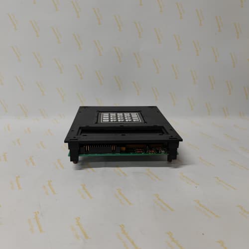
Description
Technical Parameters & Electrical Specifications
Precise electrical characterization of the 531X133PRUABG1 is essential for proper integration:
-
Microcontroller: Custom GE ASIC (Application-Specific Integrated Circuit) running at 16 MHz, executing real-time PID loops with a deterministic scan cycle of 2.2 ms—identical to the PRUAAG1 but with optimized interrupt handling for encoder signals.
-
Analog Inputs: 4 fully differential channels, software-configurable for ±10V DC, 0–10V DC, or 4–20 mA. Input impedance is rated at >15 MΩ in voltage mode (improved from the PRUAAG1’s 12 MΩ), providing better performance with high-resistance tachometer sources.
-
Analog Outputs: 2 isolated channels delivering 0–10V DC or 4–20 mA, used to command the power bridge firing boards. The output update rate on the 531X133PRUABG1 is 500 Hz with an additional slew-rate limiter to prevent abrupt torque changes.
-
Digital I/O: 8 opto-isolated digital inputs (24V DC, sink/source capable) and 6 transistor outputs (24V DC, 0.5A continuous, with integrated flyback diodes and short-circuit protection).
-
Onboard Potentiometers: 12 precision 25-turn trim-pots for offset, gain, zero, servo stiffness, and a new “tachometer damping” adjustment—exclusive to the 531X133PRUABG1—which allows engineers to suppress high-frequency noise on long feedback cables.
-
Status Indication: Enhanced LED array (red/green/yellow) providing real-time feedback on processor health, communication activity, fault latch status, and a dedicated “tachometer present” indicator.
-
Operating Temperature: 0°C to +60°C (extended range).
-
Storage Temperature: -40°C to +85°C.
-
Humidity: 5% to 95% non-condensing, with upgraded conformal coating tested for 1000 hours in salt-spray environments.
Advantages & Distinctive Features
The 531X133PRUABG1 offers several significant improvements over both its predecessors and generic alternatives:
-
Enhanced Tachometer Input Stage: The 531X133PRUABG1 incorporates a dedicated differential amplifier with active filtering specifically tuned for tachometer signals. This revision was developed in response to field complaints about speed oscillation in installations with cable runs exceeding 50 meters. The 531X133PRUABG1 reliably handles tachometer amplitudes as low as 5V peak-to-peak, whereas earlier boards required a minimum of 10V.
-
Slew-Rate Limited Outputs: Unlike the PRUAAG1, the 531X133PRUABG1 includes a programmable slew-rate limiter on its analog outputs. This feature prevents instantaneous torque reversals that can cause mechanical shock to gearboxes and couplings—a critical advantage in high-inertia applications like flywheel drives and large centrifuges.
-
Superior Thermal Compensation: The 531X133PRUABG1 uses temperature-compensated resistor networks on its gain-setting stages. This reduces drift from 100 ppm/°C on earlier boards to just 25 ppm/°C, ensuring that a drive calibrated at 20°C remains accurate even when the cabinet reaches 55°C.
-
Diagnostic Depth: The 531X133PRUABG1 provides a 4-bit fault code via its LED matrix, decoding into 16 error conditions. New additions include specific codes for “tachometer signal loss,” “tachometer polarity reversal,” “field economy mode fault,” and “armature current imbalance.”
-
Backward Compatibility: While designed for late-model DC300 cabinets, the 531X133PRUABG1 can be used in systems originally specified for the PRUAAG1 or PROAG1, provided the firmware checksum is verified. This makes the 531X133PRUABG1 a versatile spare for plants with mixed DC300 revisions.
Application Fields & Real-World Use Cases
The 531X133PRUABG1 is deployed across heavy industrial sectors requiring precise, reliable DC motor control in challenging environments:
-
Steel & Aluminum Hot Rolling Mills: The 531X133PRUABG1 manages edger drives and roughing stands, where the slew-rate limited outputs prevent mechanical shock during billet entry.
-
Paper & Tissue Machines: In winder drives and calender stacks, the 531X133PRUABG1 provides the tension control accuracy required for tissue grades, where even minor speed fluctuations cause web breaks.
-
Crane & Hoist Applications: Overhead bridge cranes and port container handlers utilize the 531X133PRUABG1 for its enhanced thermal compensation, ensuring smooth load acceleration in unventilated cab-mounted drive enclosures.
-
Mine Winders & Slope Conveyors: The 531X133PRUABG1 controls separately excited DC motors in underground mining, where its conformal coating protects against humidity, dust, and corrosive methane byproducts.
-
Test Dynamometers: Automotive and aerospace laboratories employ the 531X133PRUABG1 to control absorption dynamometers, leveraging its low-drift analog inputs for accurate torque and speed measurement over multi-hour test cycles.
Comparison with Competing / Replacement Models
When evaluating the 531X133PRUABG1 against alternatives, the following distinctions are critical:
| Aspect | 531X133PRUABG1 (GE Fanuc) | 531X133PRUAAG1 (Earlier) | Siemens 6RA70/6RA80 | ABB DCS800 |
|---|---|---|---|---|
| Tachometer Input Sensitivity | 5V p-p minimum | 10V p-p minimum | Digital encoder only (no analog tach) | Digital encoder only (no analog tach) |
| Output Slew-Rate Limiter | Yes (programmable) | No | Yes (software) | Yes (software) |
| Thermal Drift (Gain) | 25 ppm/°C | 100 ppm/°C | <10 ppm/°C (digital) | <10 ppm/°C (digital) |
| Onboard Tuning Pots | 12 (including tach damping) | 12 (no tach damping) | 0 (fully software) | 0 (fully software) |
| Drop-in Compatibility | Direct fit for mid/late DC300 | Direct fit for late DC300 | Requires full drive swap | Requires full drive swap |
| Availability | Aftermarket/refurbished | Aftermarket/refurbished | Active production | Active production |
Critical insight: The 531X133PRUABG1 is not a universal replacement for the PROAG1. The hardware changes—particularly the increased input impedance and revised filtering—mean that a PROAG1 installed in a system calibrated for a PRUABG1 will exhibit noisier speed readings and potential fault trips. Always verify the exact revision required by your drive’s configuration database before procurement.
Selection Guidelines & Sourcing Precautions
When procuring a 531X133PRUABG1, adhere to these stringent rules:
-
Revision Verification: The 531X133PRUABG1 has a specific firmware checksum and a visible “B” in the suffix. Request the supplier to provide a high-resolution photo of the board’s label and a test report showing the revision string. Beware of sellers who list PRUAAG1 or PROAG1 as PRUABG1—the components differ.
-
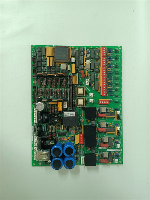
Capacitor Condition: Inspect the 531X133PRUABG1 for bulging or leaking electrolytic capacitors, particularly the 470µF, 1000µF, and 2200µF units near the power input section. Even with the upgraded 105°C rating, age and heat are the primary failure modes.
-
Potentiometer Integrity: The 12 trim-pots on the 531X133PRUABG1 are precision 25-turn sealed units. Verify that they rotate smoothly without dead spots or excessive looseness; seized or jumpy pots indicate moisture ingress or thermal damage.
-
Test Documentation: Demand a functional test certificate that includes:
-
Analog input linearity (error < 0.1% of full scale) at both 25°C and 55°C
-
Analog output accuracy (error < 0.2% of full scale) with slew-rate verification
-
Digital I/O loopback test
-
Tachometer input sensitivity test (down to 5V p-p)
-
24-hour burn-in at 55°C with monitored current loop stability
-
-
Warranty: Only purchase from suppliers offering a minimum 1-year warranty on the 531X133PRUABG1, with a clear return policy if the board fails to initialize in your specific DC300 cabinet. Some aftermarket suppliers provide 2-year warranties—prioritize those.
-
Anti-Static Handling: The 531X133PRUABG1 contains CMOS devices sensitive to electrostatic discharge. Always store and ship in anti-static bags with proper ESD labeling. Upon receipt, inspect the bag integrity before opening.
Installation & Operational Precautions
-
Power Bus Discharge: Before inserting or removing the 531X133PRUABG1, ensure the DC bus capacitors are fully discharged. Use a voltmeter to confirm less than 5V on the main DC terminals—this may take up to 10 minutes after power-off. Failure to do so can destroy the board’s power regulation circuitry.
-
ESD Protocol: Wear a grounded wrist strap and work on an ESD-safe mat. The 531X133PRUABG1‘s edge connector and component leads are particularly susceptible; even a 30V static discharge can degrade the ASIC’s input protection.
-
Cable Separation: Maintain at least 300 mm (12 inches) between analog feedback cables (tachometer, encoder) and AC power/armature cables. The 531X133PRUABG1‘s improved filtering is effective, but physical separation remains the best noise countermeasure—particularly critical for the sensitive tachometer input.
-
Potentiometer Recording: Prior to removing an old board, use a multimeter to record the resistance value of each of the 12 trim-pots (measure between wiper and each end). Transfer these settings to the new 531X133PRUABG1 as a starting point, then perform a full drive calibration according to the GE DC300 service manual.
-
Tachometer Damping Adjustment: On the 531X133PRUABG1, the new “tachometer damping” pot should be set based on cable length. As a rule of thumb: for cables under 30 meters, set to minimum; for 30–60 meters, set to midpoint; for over 60 meters, set to maximum. Fine-tune by observing speed stability on an oscilloscope.
-
Firmware Lock: Do not attempt to reprogram or alter the firmware on the 531X133PRUABG1. The microcontroller is factory-locked with a proprietary GE bootloader; any unauthorized write attempt will permanently brick the board.
-
Environmental Control: Ensure the cabinet’s ambient temperature does not exceed 55°C at the 531X133PRUABG1‘s location. If necessary, add a spot cooler or redirect airflow to prevent premature capacitor aging. The thermal compensation is excellent, but it cannot compensate for prolonged operation above 60°C.
A-B 1785-LT2
GE IC670ALG310
Foxboro FBM219
Bentley 3500/15-02-02-00
.jpg)

Reviews
There are no reviews yet.