
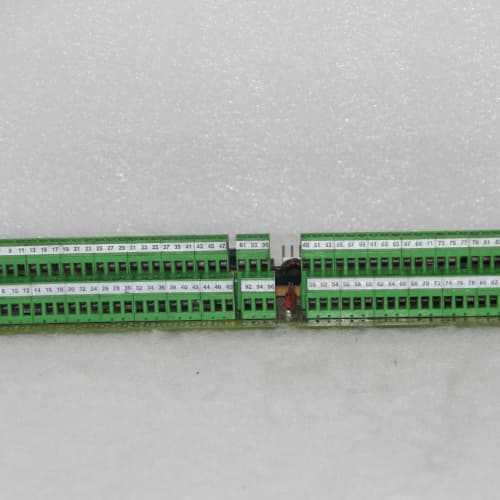
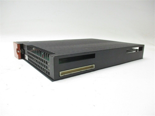
Description
Product Parameters
| Parameter | Specification |
|---|---|
| Model | 531X121PCRAHG3 |
| Manufacturer | GE Energy / GE Power Conversion |
| Series | 531X Drive Control Series |
| Type | Power control/relay board |
| Application | Drive system power control and relay switching |
| Relay Outputs | 12 channels (Form C, changeover) |
| Relay Contact Rating | 10 A at 250 VAC / 30 VDC (resistive) |
| Relay Inrush Capability | 15 A for 100 ms |
| Relay Contact Material | Silver‑tin‑oxide (AgSnO₂) with gold‑plated overlay |
| Surge Suppression | Integrated flyback diode and RC snubber |
| Control Inputs | 16 channels (optically isolated, 24 VDC) |
| Diagnostics | Built‑in self‑test (BIST), coil fault detection, contact weld detection, output current monitoring, temperature monitoring, relay cycle counting |
| Communication Interface | Isolated serial (RS‑485) with Modbus RTU protocol and isolated Ethernet (Modbus TCP) with web interface for remote monitoring and control |
| LED Indicators | Power, Status (RUN/FAIL), Relay Status (per channel), Input Status (per channel), Diagnostic Alert, Communication Active, Component Health Warning |
| Operating Temperature | -40°C to +75°C |
| Storage Temperature | -40°C to +85°C |
| Humidity | 5% to 100% (non‑condensing) |
| Power Supply | +5 VDC, ±15 VDC, +24 VDC (from base board or external) |
| Isolation | 2000 V (control‑to‑contacts), 1500 V (input‑to‑backplane, communication‑to‑backplane) |
| Conformal Coating | Yes (double-layer acrylic, MIL‑I‑46058C compliant) |
| Dimensions | Standard GE drive board form factor (approx. 300 mm x 200 mm) |
| Weight | Approx. 1.1 kg |
| MTBF | > 160,000 hours |
Advantages and Key Features
-
Form C (Changeover) Relay Outputs – The 531X121PCRAHG3 provides 12 Form C relay outputs, offering both normally open (NO) and normally closed (NC) contacts for flexible control and fail‑safe applications.
-
High Current Relay Outputs – Provides 12 relay outputs rated for 10 A at 250 VAC / 30 VDC with 15 A inrush capability, enabling direct control of high‑power loads.
-
Gold‑Plated Contacts – AgSnO₂ contacts with gold‑plated overlay on the 531X121PCRAHG3 provide superior corrosion resistance for reliable switching in harsh and corrosive environments.
-
Comprehensive Diagnostics – Built‑in self‑test (BIST), coil fault detection, contact weld detection, output current monitoring, temperature monitoring, and relay cycle counting on the 531X121PCRAHG3 enable comprehensive predictive maintenance.
-
Relay Cycle Counting – The 531X121PCRAHG3 tracks relay switching cycles, enabling predictive replacement based on actual usage rather than time‑based schedules.
-
Dual Communication Interfaces – Isolated RS‑485 (Modbus RTU) and isolated Ethernet (Modbus TCP) with integrated web interface on the 531X121PCRAHG3 provide flexible remote monitoring and control options.
-
Extended Temperature Range – Rated for -40°C to +75°C, making the 531X121PCRAHG3 suitable for the most extreme industrial environments.
-
Double‑Layer Conformal Coating – Provides protection against moisture, dust, salt spray, and chemical exposure in harsh environments.
-
Highest Reliability – > 160,000 hours MTBF on the 531X121PCRAHG3 provides the highest reliability in the 121‑series.
Application Fields and Use Cases
1. Large GE Drive Systems
The 531X121PCRAHG3 provides comprehensive Form C relay outputs for GE drive control boards (531X100CCHAPM1, 531X100CCHARM1, 531X100CCHBCG1) in large rolling mills, mine hoists, and other heavy industrial drives.
2. Turbine Auxiliary Control Panels with Fail‑Safe
Provides Form C relays with NC contacts for fail‑safe control in turbine auxiliary systems, including fuel control, lube oil pumps, cooling fans, and hydraulic systems. NC contacts maintain critical functions when control power is lost.
3. Motor Starter Control with Fail‑Safe
The 531X121PCRAHG3 provides 10 A Form C outputs with contact weld detection for direct control of motor starters with normally closed contacts for fail‑safe operation.
4. Solenoid Actuation
Provides high‑current Form C relay outputs for controlling solenoid‑operated valves with both energize‑to‑operate and de‑energize‑to‑operate options.
5. Alarm and Annunciation
The 531X121PCRAHG3 controls annunciator panels, horns, and indicating lights with both NO and NC contact flexibility and remote monitoring.
6. Retrofit and Upgrade
The 531X121PCRAHG3 is the recommended upgrade for Form C relay applications requiring maximum capacity and advanced diagnostics.
Comparison with Competing Products
| Feature | 531X121PCRAHG3 (GE) | 531X121PCRAHG1 (GE) | 531X121PCRAGG3 (GE) | 531X121PCRAEG1 (GE) | ABB DO880 + TU830 |
|---|---|---|---|---|---|
| Series | 531X121 | 531X121 | 531X121 | 531X121 | ACS800/880 |
| Relay Outputs | 12 (Form C) | 8 (Form C) | 16 (Form A) | 12 (Form A) | 16 (Form A, 2 A) |
| Contact Rating | 10 A (15 A inrush) | 10 A | 10 A (15 A inrush) | 10 A | 2 A |
| NO/NC Contacts | Both | Both | NO only | NO only | NO only |
| Control Inputs | 16 | 8 | 16 | 16 | N/A |
| Gold‑Plated Contacts | Yes | No | Yes | No | No |
| Relay Cycle Counting | Yes | No | Yes | No | No |
| Diagnostics | BIST, coil fault, weld, current, temp, cycle count | No | BIST, coil fault, weld, current, temp, cycle count | BIST, coil fault, weld, current | Limited |
| Communication | RS‑485 + Ethernet (web) | No | RS‑485 + Ethernet (web) | No | No |
| Conformal Coating | Double-layer | No | Double-layer | No | No |
| Temp Range | -40°C to +75°C | 0°C to +55°C | -40°C to +75°C | -10°C to +60°C | -25°C to +60°C |
| MTBF | > 160,000 hrs | > 100,000 hrs | > 160,000 hrs | > 120,000 hrs | > 120,000 hrs |
Key Differentiators: The 531X121PCRAHG3 is the ultimate Form C power control board in the 121‑series, offering 12 high‑current (10 A, 15 A inrush) Form C relay outputs (both NO and NC), 16 optically isolated control inputs, gold‑plated contacts, comprehensive diagnostics (BIST, coil fault, contact weld, current monitoring, temperature monitoring, relay cycle counting), dual communication interfaces (RS‑485 Modbus + Ethernet Modbus TCP with web interface), double‑layer conformal coating, and extended temperature range (-40°C to +75°C). It is the definitive choice for the most demanding power control applications requiring Form C relays, predictive maintenance, remote monitoring, and extreme environmental protection.
Selection Suggestions and Precautions
Selection Criteria
-
Choose the 531X121PCRAHG3 for GE 531X drive applications requiring Form C relay outputs (both NO and NC contacts) with maximum capacity (12 channels), advanced diagnostics, remote monitoring, and extreme environmental protection.
-
For Form C applications with lower I/O requirements or standard environments, consider the 531X121PCRAHG1 (8 channels) at lower cost.
-
For applications requiring Form A outputs only, consider the 531X121PCRAGG3 (16 channels).
-
Verify compatibility with the base drive control board (531X100CCHAPM1, 531X100CCHARM1, or 531X100CCHBCG1).
-
Ensure the 531X121PCRAHG3 relay contact rating (10 A) is sufficient for the connected loads.
Critical Precautions
-
Load Rating – Ensure field device current does not exceed the 531X121PCRAHG3 contact rating (10 A continuous, 15 A inrush). For inductive loads, apply appropriate derating (typically 50% of resistive rating) and use external surge suppression for high‑inductance loads.
-
NC Contact Usage – When using the normally closed (NC) contacts of the 531X121PCRAHG3, ensure the load is within the contact rating at all times, including during relay coil energization.
-
Output Wiring – Use appropriate wire gauge for relay outputs based on load current. Keep relay wiring separated from signal wiring to prevent transient coupling.
-
Communication Wiring – For RS‑485 (Modbus RTU), use shielded twisted‑pair cable. For Ethernet (Modbus TCP), use CAT5e shielded cable. The integrated web interface provides easy access to relay status and diagnostic data.
-
Relay Cycle Counting – Use the relay cycle counting feature of the 531X121PCRAHG3 for predictive maintenance. Replace relays approaching their rated life based on actual usage.
-
Diagnostic Monitoring – Use the diagnostic features of the 531X121PCRAHG3 (coil fault, contact weld, current monitoring, temperature monitoring) to monitor relay health and environmental conditions.
-
Compatibility Verification – Verify the 531X121PCRAHG3 is compatible with your base drive board revision.
-
Grounding – Ensure the 531X121PCRAHG3 is properly grounded to prevent noise and ensure safety.
-
Cooling – Maintain adequate airflow for the 531X121PCRAHG3 to prevent overheating. At high ambient temperatures, forced air is recommended.
-
ESD Handling – Use grounded wrist straps when handling the 531X121PCRAHG3 to prevent static damage.
-
Obsolescence – The 531X121PCRAHG3 is legacy production. For new drive applications, evaluate modern GE relay output solutions. Keep spare units for critical large‑scale, extreme‑environment drive applications.
A-B 1746-NIO4V
A-B 1746-NIO4I
AB 1746-NI8

.jpg)


Reviews
There are no reviews yet.