
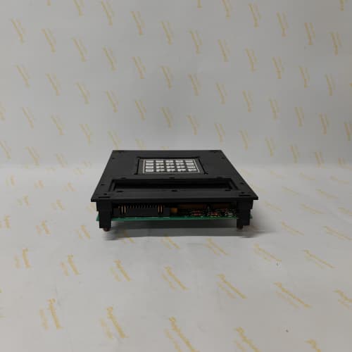
Description
Product Parameters
| Parameter | Specification |
|---|---|
| Model | 531X100CCHBCG1 |
| Manufacturer | GE Energy / GE Power Conversion |
| Series | 531X Drive Control Series |
| Type | Bridge/converter control board |
| Application | AC/DC power conversion bridge control |
| Converter Types | Thyristor (SCR) bridges, IGBT inverters, regenerative converters |
| Gate Drive Outputs | 6–12 channels (for SCR/IGBT/IGCT control) |
| Firing Pulse Generation | Phase-angle control for thyristors; PWM for IGBTs |
| Analog Inputs | 4 channels (configurable: 0–10 V, ±10 V, 4–20 mA) |
| Analog Outputs | 2 channels (configurable: 0–10 V, 4–20 mA) |
| Digital Inputs | 6 channels (optically isolated, 24 VDC) |
| Digital Outputs | 4 channels (relay or solid‑state) |
| Feedback Interface | Current transformers, voltage transformers, Hall-effect sensors |
| Synchronization | Line voltage synchronization (zero-crossing detection) |
| Protection Features | Overcurrent, short‑circuit, phase loss, commutation failure, overtemperature, instantaneous trip |
| Diagnostics | Built‑in self‑test (BIST), fault logging, gate drive monitoring, real‑time performance monitoring |
| LED Indicators | Power, Status (RUN/FAIL), Gate Active, Fault (per channel), Synchronization Status |
| Communication Ports | RS‑232, RS‑485, optional fieldbus (Profibus, Modbus) |
| Operating Temperature | 0°C to +55°C |
| Storage Temperature | -40°C to +85°C |
| Humidity | 5% to 95% (non‑condensing) |
| Power Supply | +5 VDC, ±15 VDC, +24 VDC (external or backplane) |
| Dimensions | Standard GE drive board form factor (approx. 300 mm x 200 mm) |
| Weight | Approx. 1.1 kg |
| MTBF | > 100,000 hours |
Advantages and Key Features
-
Optimized Bridge Control – The 531X100CCHBCG1 is specifically designed for controlling thyristor (SCR) bridges and IGBT converters, providing reliable gate drive signals and precise firing pulse generation.
-
Multiple Converter Support – Supports thyristor phase‑angle control for DC drives, PWM control for AC inverters, and regenerative converter control, providing flexibility for various drive topologies.
-
Line Synchronization – Includes dedicated line voltage synchronization (zero‑crossing detection) for the 531X100CCHBCG1, ensuring accurate firing pulse timing for thyristor bridge control.
-
Comprehensive Protection – Built‑in overcurrent, short‑circuit, phase loss, commutation failure, and overtemperature protection on the 531X100CCHBCG1 ensure reliable drive operation and protection against power stage faults.
-
Gate Drive Monitoring – The 531X100CCHBCG1 includes continuous gate drive monitoring, detecting open‑circuit, short‑circuit, and missing firing pulses for enhanced reliability.
-
Configurable I/O – Analog and digital I/O on the 531X100CCHBCG1 are configurable for a wide range of signals, providing flexibility for various field devices and control schemes.
-
Robust Diagnostics – Built‑in self‑test (BIST), fault logging, and real‑time performance monitoring enable predictive maintenance and rapid troubleshooting.
-
High Channel Density – Provides up to 12 gate drive channels in a single module, reducing board count in large drive systems.
Application Fields and Use Cases
1. Thyristor DC Drive Control
The 531X100CCHBCG1 provides phase‑angle firing pulses for thyristor bridges in large DC motor drives (up to several MW), including rolling mills, mine hoists, and turbine auxiliary systems.
2. AC Variable Frequency Drive (VFD) Control
Provides PWM gate signals for IGBT power modules in AC drives for pumps, fans, compressors, and other variable torque loads.
3. Regenerative Braking Systems
The 531X100CCHBCG1 controls regenerative converter bridges for regenerative braking in hoists, elevators, and testing applications.
4. Turbine Synchronous Motor Starters
Provides bridge control for starting large synchronous motors used as turbine starters or in auxiliary systems.
5. Power Supply Converters
Controls AC‑DC converters and DC‑DC converters in industrial power supplies and battery charging systems.
6. Retrofit Applications
The 531X100CCHBCG1 is used in retrofit projects to upgrade legacy bridge control boards in GE drive systems, providing modern control capability.
Comparison with Competing Products
| Feature | 531X100CCHBCG1 (GE) | 531X100CCHARM1 (GE) | ABB DCS800 Bridge Board | Siemens 6RA7095-6DS22-0 |
|---|---|---|---|---|
| Series | 531X Drive Control | 531X Drive Control | DCS800 | SIMOREG |
| Type | Bridge/converter control | Armature control board | Bridge control | Bridge control |
| Application | SCR/IGBT converter control | Armature regulation | SCR bridge | SCR bridge |
| Gate Drive Outputs | 6–12 channels | 6 channels | 6 channels | 6 channels |
| Converter Types | Thyristor, IGBT, regenerative | Thyristor, IGBT | Thyristor | Thyristor |
| Line Sync | Yes (zero‑crossing) | No | Yes | Yes |
| Gate Monitoring | Yes | Limited | Yes | Yes |
| Protection | Comprehensive | Comprehensive | Comprehensive | Comprehensive |
| Temp Range | 0°C to +55°C | 0°C to +55°C | 0°C to +50°C | 0°C to +40°C |
| MTBF | > 100,000 hrs | > 100,000 hrs | > 100,000 hrs | > 80,000 hrs |
Key Differentiators: The 531X100CCHBCG1 is specifically optimized for thyristor bridge control with dedicated line synchronization and gate drive monitoring. It supports multiple converter topologies (SCR, IGBT, regenerative) and provides comprehensive protection against bridge‑related faults.
Selection Suggestions and Precautions
Selection Criteria
-
Choose the 531X100CCHBCG1 for applications requiring precise control of thyristor bridges, IGBT inverters, or regenerative converters.
-
Verify compatibility with your existing GE drive system (DC2000, DC3000, etc.).
-
Ensure the 531X100CCHBCG1 gate drive outputs are compatible with the power module firing requirements (voltage, current, isolation).
-
Ensure proper cooling and mounting for the 531X100CCHBCG1 in the drive cabinet.
Critical Precautions
-
Line Synchronization – Ensure proper line voltage connection to the 531X100CCHBCG1 synchronization inputs. Incorrect phase or voltage may cause firing pulse errors.
-
Gate Drive Compatibility – Verify the 531X100CCHBCG1 gate drive voltage and current are compatible with the power module (IGBT, SCR, IGCT) requirements.
-
Power Supply Verification – Verify the 531X100CCHBCG1 power supply voltages (+5 VDC, ±15 VDC, +24 VDC) are within tolerance. Incorrect voltages may damage the board.
-
Gate Drive Wiring – Use proper isolation and shielding for gate drive connections. Short circuits may damage the 531X100CCHBCG1.
-
ESD Handling – Use grounded wrist straps when handling the 531X100CCHBCG1 to prevent static damage.
-
Firmware Compatibility – Ensure the 531X100CCHBCG1 firmware matches the drive application and hardware revision.
-
Protection Settings – Configure protection thresholds on the 531X100CCHBCG1 to match the drive system ratings.
-
Cooling – Maintain adequate airflow for the 531X100CCHBCG1 to prevent overheating.
-
Obsolescence – The 531X100CCHBCG1 is legacy production. For new drive applications, evaluate modern GE drive control solutions. Keep spare boards for critical bridge control applications.
SIEMENS 6ES7972-0CB20-0XA0
GE IC200PBI001
ABB RETA-02
ABB DP820



Reviews
There are no reviews yet.