
Description
Technical Specifications
-
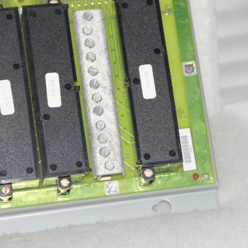
Product Type: Servo Feedback Conditioning Board (Revision 1A1A)
-
Part Number: DS3800DSFC1A1A
-
Manufacturer: General Electric (GE)
-
System Compatibility: GE Speedtronic Mark IV Turbine Control Systems
-
Input Channels: 8 differential feedback inputs
-
Input Types: LVDT, RVDT, Resolver
-
Excitation Output: Fixed 5Vrms @ 2.5kHz (selectable via jumpers for 2.5kHz or 5kHz)
-
Demodulation: Synchronous demodulation with fixed phase correction (factory-set)
-
Output: ±10Vdc analog signal per channel
-
Filtering: Fixed low-pass filter at 100Hz (hardware)
-
Isolation: 1500Vrms opto-isolation
-
Temperature Range: 0°C to +60°C
-
MTBF: > 150,000 hours (MIL-HDBK-217F)
Key Features & Advantages
-
Field-Proven Reliability: The GE DS3800DSFC1A1A uses discrete through-hole components with a long track record in GE turbines worldwide. This revision is known for its robustness and repairability.
-
Fixed but Reliable Excitation: Factory-set 5Vrms @ 2.5kHz (jumper-selectable to 5kHz) provides stable excitation for most standard LVDT/RVDT sensors.
-
Synchronous Demodulation: The GE DS3800DSFC1A1A uses analog synchronous demodulation, ensuring < 0.05% linearity error and < 0.02% per °C drift.
-
Fixed Phase Correction: Factory-optimized phase compensation eliminates the need for field adjustment in most applications.
-
Diagnostic LEDs: Front-panel LEDs indicate excitation presence, signal amplitude, and fault status for each of the 8 channels.
-
Compact 8-Channel Design: Supports multiple feedback devices on a single board, saving rack space.
Typical Application Cases
-
Servo Valve Position Feedback: Conditions LVDT signals from servo valves, providing position feedback to the Mark IV processor for closed-loop control.
-
Actuator Stroke Monitoring: Processes RVDT signals from hydraulic actuators on steam turbine main stop and control valves.
-
IGV Position Sensing: Conditions feedback from inlet guide vane position sensors in gas turbine compressors.
-
Thrust Bearing Monitoring: Monitors LVDTs measuring turbine thrust position, detecting axial movement and preventing bearing failure.
Competitive Comparison
| Feature | GE DS3800DSFC1A1A | GE DS3800DSFC (Base) | Modern Feedback Module |
|---|---|---|---|
| Excitation | Fixed 5V @ 2.5/5kHz | Programmable (2.5-10V, 2-10kHz) | Fixed (3V typical) |
| Phase Correction | Fixed (factory-set) | Adjustable | Software-programmable |
| Filtering | Fixed 100Hz | Selectable 10Hz-1kHz | Software-configurable |
| Demodulation | Synchronous (analog) | Synchronous (analog) | Digital (software) |
| Output Type | ±10Vdc | ±10Vdc | Digital fieldbus |
| Isolation | 1500Vrms | 1500Vrms | 500Vrms |
| Compatibility | Mark IV backplane | Mark IV backplane | Universal fieldbus |
The GE DS3800DSFC1A1A is a simpler, fixed-configuration version of the base DS3800DSFC. It offers proven reliability for standard LVDT/RVDT applications but lacks the flexibility of later revisions.
Selection Guidelines & Precautions
-
Feedback Device Verification: Confirm your LVDT/RVDT specifications (primary impedance, excitation requirements) match the GE DS3800DSFC1A1A fixed 5V excitation. If your sensor requires different voltage or frequency, use a later revision instead.
-
Phase Correction: The GE DS3800DSFC1A1A has fixed phase compensation. If your feedback sensor has unusual electrical characteristics (e.g., long cable runs > 100m), verify demodulator output with an oscilloscope. Consider upgrading to a programmable revision if phase error is significant.
-
Filter Limitation: Fixed 100Hz filtering may not remove all high-frequency noise in environments with VFDs or ignition transformers. For noisy installations, consider adding external filters or upgrading to a revision with adjustable filtering.
-
Cable Shielding: Use shielded twisted-pair cables for all feedback connections. Ground shield at the GE DS3800DSFC1A1A end only to prevent ground loops.
-
ESD Handling: Use ESD-safe practices; contains sensitive analog front-end components.
-
Commissioning: Verify output voltage corresponds correctly to LVDT position using a calibrated position simulator. Use diagnostic LEDs to confirm excitation presence on all 8 channels.
-
Sourcing: Obsolete. Request functional test report including:
-
All 8 channels tested with LVDT/RVDT simulator
-
Excitation voltage and frequency verification
-
Demodulation linearity test (< 0.05% error)
-
Output offset and gain calibration
-
-
Spare Strategy: Keep one spare GE DS3800DSFC1A1A on-site. For turbines with critical feedback loops, consider redundant feedback conditioning using two boards in parallel.
A-B 1746-IM16/C
GE IC693MDL930
MODICON AS-BADU-204




Reviews
There are no reviews yet.