
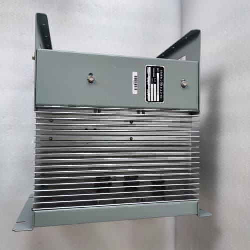
Description
Technical Specifications
-
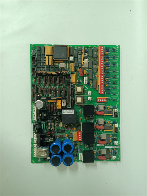
Product Type: Digital Relay & Flag Output Board (Revision 1B1A)
-
Part Number: DS3800DRFA1B1A
-
Manufacturer: General Electric (GE)
-
System Compatibility: GE Speedtronic Mark IV Turbine Control Systems
-
Output Channels: 16 digital outputs (Form C – SPDT relays)
-
Contact Rating: 5A @ 250VAC/30VDC (resistive); 2A @ 250VAC (inductive)
-
Surge Suppression: Enhanced RC snubber + bidirectional TVS diodes (upgraded from standard flyback)
-
Indicators: Mechanical latching flags + front-panel status LEDs per channel
-
Isolation: 2500Vrms opto-isolation (logic-to-field), upgraded from 1500Vrms
-
Temperature Range: -40°C to +70°C (extended, vs. 0-60°C base)
-
Backplane Interface: 50-pin edge connector; compatible with Mark IV Rev. L and later
-
MTBF: > 150,000 hours (MIL-HDBK-217F)
Key Features & Advantages
-
Latching Relays with Mechanical Flags: Maintains trip states after power loss; flags provide instant visual confirmation of relay status without tools.
-
Enhanced Surge Suppression: Upgraded TVS diodes and RC networks protect against high-energy inductive spikes from large solenoids and contactors, reducing contact wear and extending relay life.
-
Extended Temperature Range: Rated -40°C to +70°C, suitable for outdoor or unheated turbine enclosures in harsh climates.
-
Higher Isolation Voltage: 2500Vrms (vs. 1500Vrms base) provides better protection against ground loops and voltage transients in industrial environments.
-
Form C Contact Flexibility: Each channel offers both NO and NC contacts, supporting energize-to-trip and de-energize-to-trip configurations.
-
Diagnostic LEDs: Front-panel LEDs indicate coil energization, complementing mechanical flags for quick troubleshooting.
Typical Application Cases
-
Emergency Trip Valve Control: The GE DS3800DRFA1B1A drives the solenoid valves for main fuel shut-off and emergency stop valves. In de-energize-to-trip systems, the relay remains energized during normal operation, and upon a trip command, it de-energizes to close the valve – a fail-safe design.
-
Alarm Annunciator Panels: Drives visual/audible alarms for overspeed, high bearing temperature, or low lube oil pressure. Mechanical flags retain alarm history after power cycles.
-
Auxiliary Motor Start/Stop: Controls lube oil pumps, turning gear motors, and jacking oil pumps during turbine startup and shutdown sequences.
-
Compressor Bleed Valve Actuation: Controls bleed valves to prevent compressor surge during startup and load changes; fast response (<10ms) ensures rapid actuation.
Competitive Comparison
| Feature | GE DS3800DRFA1B1A | Modern PLC Output Module (e.g., Siemens 6ES7522-5FH00) |
|---|---|---|
| Output Type | Electromechanical relay (Form C) | Solid-state transistor |
| Contact Rating | 5A @ 250VAC/VDC | 0.5A @ 24VDC |
| Isolation | 2500Vrms (opto + relay) | 500Vrms |
| Visual Indication | Mechanical flags + LEDs | LEDs only |
| Latching | Yes (magnetic, retains state) | No (software only, lost on power cycle) |
| Surge Suppression | Built-in TVS + RC | External required |
| Temperature Range | -40°C to +70°C | 0°C to +60°C |
| Compatibility | Dedicated Mark IV | Universal Profinet |
Modern solid-state modules switch faster and last longer, but cannot handle high-current inductive loads directly. The GE DS3800DRFA1B1A remains essential for direct actuator control due to its high current capacity and galvanic isolation. For Mark IV systems, this board is irreplaceable without major cabinet re-engineering.
Selection Guidelines & Precautions
-
Load Current Verification: Confirm field device current draw. For inductive loads (solenoids, contactors), derate to 2A. If exceeding 2A, use the GE DS3800DRFA1B1A to drive an external interposing relay.
-
Latching Relay Reset: Relays maintain state after power loss. After a trip, a reset signal from the Mark IV processor (or manual reset) is required. If not reset, the GE DS3800DRFA1B1A will prevent turbine restart.
-
Backplane Compatibility: The GE DS3800DRFA1B1A requires a Mark IV backplane Rev. L or later. For older racks, verify pin compatibility; adapter boards may be needed for the enhanced isolation circuits.
-
Flag Indicator Maintenance: Mechanical flags can stick after long idle periods. During commissioning, cycle each channel several times to ensure free movement and accurate indication.
-
ESD Handling: Use ESD-safe practices; opto-isolators on the logic side are sensitive to static damage.
-
Shielded Wiring: Use shielded cables for field wiring, especially with inductive loads, to prevent noise coupling into adjacent analog circuits in the rack.
-
Sourcing: The GE DS3800DRFA1B1A is obsolete; only available through aftermarket suppliers. Request a functional test report including:
-
All 16 channels tested under load
-
Mechanical flag operation verified
-
Contact resistance < 0.1Ω (new) or < 0.5Ω (refurbished)
-
Surge suppression functionality confirmed
-
Capacitors replaced (if aged)
-
-
Spare Strategy: Keep at least one spare GE DS3800DRFA1B1A on-site. For critical trip circuits, consider redundant configuration (two boards in series) to ensure fail-safe operation if one board fails.
A-B 1746-A10
A-B 1746-A10
HONEYWELL H7080B3273

.jpg)

Reviews
There are no reviews yet.