
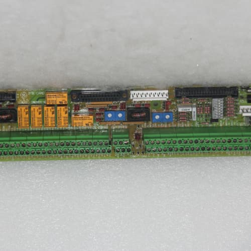
Description
Technical Parameters
-
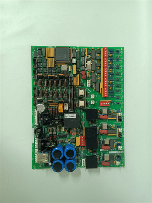
Product Type: Multi-purpose I/O expansion board
-
Digital inputs: 8 (24 VDC, opto-isolated, software-configurable as sinking or sourcing)
-
Digital outputs: 8 (24 VDC, 0.5A, protected against short circuit and overcurrent)
-
Analog inputs: 4 differential (software-configurable: 0–10V, 0–20mA, 4–20mA, ±10V)
-
Analog outputs: 2 (0–10V or 4–20mA, software-selectable, 12-bit resolution)
-
I/O configuration: Per-channel software assignment (input/output) – no jumpers required
-
Isolation: 1500 Vrms between I/O and drive logic
-
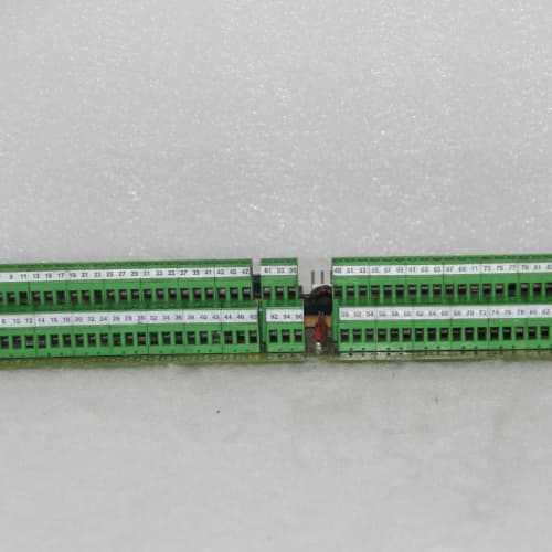
Connectors: One 26-pin header to regulator board; two 12-position terminal blocks for field wiring
-
Mounting: 4× M4 holes (standard GE rack footprint)
-
Power supply: +5 VDC and +15 VDC from regulator board
-
LED indicators: Power, Fault, and individual status LEDs for each digital I/O point
Advantages & Features
-
Software-configurable I/O – Each digital point can be independently set as input or output via drive parameters on GE 531X159MPEAMG1, eliminating hardware jumpers and reducing spare board variety
-
Flexible analog ranges – 4 analog inputs accept voltage or current without hardware changes; 2 analog outputs selectable for 0–10V or 4–20mA
-
Short-circuit protection – Digital outputs are protected against short circuits and overcurrent, reducing board failure risk
-
Galvanic isolation – 1500 Vrms protects the regulator board from field wiring faults
-
Diagnostic LEDs – Individual status LEDs for each digital point simplify troubleshooting
-
Plug-and-play – Direct replacement for earlier MPE revisions; no configuration changes needed for basic functions
Application Cases
-
Conveyor control – Material handling system used GE 531X159MPEAMG1 to read 8 photoeye inputs and control 8 motor contactor outputs, eliminating a separate PLC for simple conveyor logic
-
Pump sequencing – Water treatment plant used 4 analog inputs (pressure transducers) and 2 analog outputs (pump speed references) on GE 531X159MPEAMG1 for cascade pump control
-
Alarm monitoring – HVAC chiller plant used digital inputs for alarm contacts (high temp, low flow) and digital outputs for alarm horns, all via GE 531X159MPEAMG1 without external I/O modules
Competitive Comparison
| Aspect | GE 531X159MPEAMG1 (OEM) | Generic Aftermarket I/O Card |
|---|---|---|
| I/O configurability | Software (each point) | Fixed I/O or hardware jumpers |
| Analog input ranges | 0–10V, 0–20mA, 4–20mA, ±10V | Fixed (voltage or current only) |
| Digital output protection | Short-circuit + overcurrent | Limited or none |
| Analog output resolution | 12-bit | 8–10 bit typical |
| Isolation | 1500 Vrms | Usually non-isolated |
| Diagnostic LEDs | Per-point status | Limited or none |
Selection Suggestions
-
Choose GE 531X159MPEAMG1 when additional I/O is needed beyond the base regulator – it adds 8 digital inputs, 8 digital outputs, 4 analog inputs, and 2 analog outputs
-
Select AMG1 for applications requiring flexible I/O assignment – each digital point can be an input or output, allowing one spare board to cover multiple applications
-
Verify the number of I/O points needed – GE 531X159MPEAMG1 is ideal for mid-size expansion; for larger systems, consider multiple boards or external I/O
-
Confirm regulator board compatibility – works with 531X111, 531X139, and 531X305 series (firmware must support AMG1)
-
For analog signals, verify transducer output type (voltage or current) and set each input accordingly via drive parameters
-
Prefer remanufactured units with new optocouplers and capacitors
Precautions
-
Always disconnect power before handling GE 531X159MPEAMG1 – field wiring may carry external voltages
-
Do not exceed 24 VDC on digital inputs – higher voltage damages the optocouplers
-
Digital outputs are rated 0.5A maximum – do not connect high-current loads directly (use interposing relays for loads >0.5A)
-
Analog inputs in current mode require the internal 250Ω resistor – do not add external resistors
-
Use shielded twisted-pair cables for analog signals – unshielded cables pick up EMI
-
When replacing, transfer all I/O configuration parameters from the old GE 531X159MPEAMG1 to the new board via drive software
-
Torque mounting screws to 2–3 N·m – over-tightening cracks the PCB
-
If a digital output does not activate, check the output configuration (input vs. output) in the drive parameters – the software assignment overrides physical wiring
-
For critical I/O, use normally-closed (NC) contacts for alarms – this provides fail-safe detection on open circuits
GE IC694MDL660
SCHNEIDER TSXP57104M
Siemens 6GT2001-0AA00-0AX0
A-B 1771-ASB


Reviews
There are no reviews yet.