
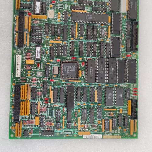
Description
Technical Parameters
-
Product Type: Speed feedback / resolver-encoder interface board
-
Input types: Resolver (sine/cosine), incremental encoder (TTL/HTL), DC tachometer (analog) – software-configurable
-
Resolver excitation: 4 Vrms / 2–10 kHz (programmable frequency)
-
Resolver-to-digital conversion: Onboard RDC with 16-bit resolution
-
Encoder channels: A, B, Z (differential or single-ended) – 1 MHz max frequency
-
Tachometer input: ±10 VDC (differential)
-
Velocity resolution: 16-bit (resolver) / 12-bit (tachometer)
-
Position resolution: Up to 65536 counts per revolution (resolver)
-
Isolation: 1500 Vrms between feedback inputs and drive logic
-
Connectors: One 26-pin header to regulator board; one 15-pin D-sub (encoder); one 6-pin terminal block (resolver/tachometer)
-
Mounting: 4× M4 holes (standard GE rack footprint)
-
Power supply: +5 VDC and +15 VDC from regulator board
-
LED indicators: Power, Fault, Lock (resolver tracking), and A/B/Z activity
Advantages & Features
-
Integrated resolver-to-digital converter – No external RDC modules required; GE 531X156TRCABG1 directly interfaces with resolvers for absolute position feedback
-
Software-selectable inputs – Feedback type selected via drive parameters, eliminating hardware jumpers and reducing installation errors
-
Programmable resolver excitation – Frequency adjustable (2–10 kHz) to match any resolver specification
-
High resolution – 16-bit position (resolver) and velocity data for precision applications
-
Encoder support – Accepts TTL or HTL encoders with 1 MHz max frequency
-
Diagnostic LEDs – “Lock” LED indicates resolver tracking lock; activity LEDs for encoder channels
-
Plug-and-play – Pin-compatible with earlier TRC and TEC revisions
Application Cases
-
Absolute positioning hoists – Overhead crane with resolver feedback used GE 531X156TRCABG1 for precise position control; the integrated RDC eliminated external resolver converters, saving cabinet space
-
High-speed servo applications – Packaging machine with 5000 PPR encoder relied on GE 531X156TRCABG1 for accurate speed regulation at 6000 RPM
-
Wind turbine pitch control – Resolver feedback in harsh environments; the programmable excitation of GE 531X156TRCABG1 allowed tuning to long cable lengths (up to 100 meters)
Competitive Comparison
| Aspect | GE 531X156TRCABG1 (OEM) | Generic Aftermarket Feedback Card |
|---|---|---|
| Resolver interface | Integrated RDC (onboard) | Requires external RDC module |
| Feedback selection | Software-configurable | Hardware jumpers or fixed |
| Resolver excitation | Programmable 2–10 kHz | Fixed frequency only |
| Position resolution | 16-bit (65536 counts/rev) | 10–12 bit typical |
| Encoder max frequency | 1 MHz | 100–500 kHz typical |
| Diagnostic LEDs | Lock + activity | Limited or none |
Selection Suggestions
-
Choose GE 531X156TRCABG1 for resolver-based applications – the integrated RDC and programmable excitation eliminate external hardware
-
Select TRC over TEC (encoder-only) when absolute position feedback is required (resolver provides absolute, encoder is incremental)
-
Verify your resolver’s excitation voltage and frequency requirements – GE 531X156TRCABG1 provides programmable frequency but fixed 4Vrms output
-
Confirm regulator board compatibility – works with 531X111, 531X139, and 531X305 series (firmware must support TRC boards)
-
For long cable runs (>50m), the programmable excitation on GE 531X156TRCABG1 allows adjustment to compensate for cable capacitance
-
Prefer remanufactured units with new RDC chips and optocouplers
Precautions
-
Always disconnect power before handling GE 531X156TRCABG1 – feedback cables may carry external voltages
-
Use shielded twisted-pair cables for resolver wiring – the sine/cosine signals are sensitive to EMI
-
Resolver excitation and feedback wires must be twisted pairs – separate excitation from feedback to avoid coupling
-
Encoder wiring requires proper termination – unterminated TTL encoders cause ringing and speed errors
-
When replacing, verify the feedback type is set correctly in the drive parameters (not jumpers) for GE 531X156TRCABG1
-
Torque mounting screws to 2–3 N·m – over-tightening cracks the PCB
-
Do not run feedback cables parallel to motor power leads – maintain at least 30 cm separation
-
If the “Lock” LED does not illuminate, check resolver wiring polarity – reversed sine/cosine connections cause tracking failure
-
For resolver installations, ground the cable shield at the drive end only (not at the resolver)
BOSCH LT303 0608750084
A-B 1756-OF4
SCHNEIDER 140ACI03000
.jpg)

Reviews
There are no reviews yet.