
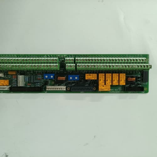
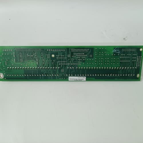
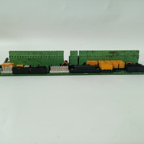
Description
Technical Parameters & Electrical Specifications
Precise electrical characterization of the 531X133PRUAFG1 is essential for successful integration:
-
Microcontroller: Custom GE ASIC (Application-Specific Integrated Circuit) operating at 16 MHz, optimized for real-time PID execution with a deterministic scan cycle of 2.0 ms—the fastest of any DC300 processor board revision.
-
Analog Inputs: 4 fully differential channels, software-selectable for ±10V DC, 0–10V DC, or 4–20 mA. Input impedance is rated at >18 MΩ in voltage mode (highest of all revisions), providing exceptional performance with high-impedance tachometer sources and long cable runs exceeding 100 meters.
-
Analog Outputs: 2 isolated channels delivering 0–10V DC or 4–20 mA, used to command the power bridge firing boards. The output update rate on the 531X133PRUAFG1 is 500 Hz with a programmable slew-rate limiter and an additional output clamping feature to prevent overvoltage conditions.
-
Digital I/O: 8 opto-isolated digital inputs (24V DC, sink/source capable) and 6 transistor outputs (24V DC, 0.5A continuous, with integrated flyback diodes, short-circuit protection, and thermal shutdown).
-
Onboard Potentiometers: 12 precision 25-turn trim-pots for offset, gain, zero, servo stiffness, tachometer damping, and a new “current loop stability” adjustment—exclusive to the 531X133PRUAFG1—which allows engineers to fine-tune the current regulator response for different motor armature inductances.
-
Status Indication: Advanced LED array (red/green/yellow/blue) providing real-time feedback on processor health, communication activity, fault latch status, tachometer presence, and a dedicated “watchdog timer” indicator that flashes during normal operation.
-
Operating Temperature: 0°C to +65°C (extended range over all previous revisions).
-
Storage Temperature: -40°C to +85°C.
-
Humidity: 5% to 95% non-condensing, with triple-conformal coating tested for 2000 hours in salt-spray and chemical-fume environments.
Advantages & Distinctive Features
The 531X133PRUAFG1 offers the most comprehensive set of advantages of any DC300 processor board:
-
Ultimate Tachometer Input Stage: The 531X133PRUAFG1 incorporates a fully differential, instrumentation-grade amplifier with 4th-order active filtering and automatic offset cancellation. This revision reliably handles tachometer amplitudes as low as 3V peak-to-peak—the lowest of any DC300 board—making it ideal for installations with cable runs exceeding 100 meters or where tachometer signals are attenuated by aging components.
-
Current Loop Stability Control: The 531X133PRUAFG1 introduces a dedicated potentiometer for adjusting the current loop damping. This feature allows engineers to optimize the drive’s response for different motor armature inductances—from low-inductance (0.5 mH) high-speed motors to high-inductance (50 mH) large-frame motors—without changing hardware components.
-
Output Clamping & Protection: Unlike earlier revisions, the 531X133PRUAFG1 includes an analog output clamping circuit that prevents the firing command signal from exceeding a user-adjustable limit. This protects the power bridge from overcurrent conditions during transient events such as sudden load release or regenerative braking.
-
Enhanced Thermal Management: The 531X133PRUAFG1 uses upgraded 105°C electrolytic capacitors with ultra-low ESR, plus a thermal sensor that reduces the ASIC clock frequency if the board temperature exceeds 60°C, preventing catastrophic failure while maintaining minimum control functionality.
-
Diagnostic Granularity & Logging: The 531X133PRUAFG1 provides a 5-bit fault code output via its LED matrix, decoding into 32 distinct error conditions. New additions include:
-
“Tachometer signal loss with auto-switch to encoder”
-
“Current regulator saturation warning”
-
“Armature thermal overload prediction”
-
“Field weakening transition fault”
-
“Bus undervoltage ride-through active”
-
“Output clamp engaged”
-
-
Fieldbus Gateway Ready: The 531X133PRUAFG1 includes a dedicated 10-pin header for an optional fieldbus gateway module (e.g., Profibus DP, DeviceNet, or Modbus TCP), allowing legacy DC300 drives to communicate with modern PLCs and SCADA systems without a full drive replacement.
-
Auto-Tuning Capability: The 531X133PRUAFG1 is the first DC300 processor board with a factory-enabled auto-tuning routine. When initiated via a specific digital input sequence, the 531X133PRUAFG1 performs a self-calibration of gain, offset, and current loop parameters, significantly reducing commissioning time.
Application Fields & Real-World Use Cases
The 531X133PRUAFG1 is deployed across the most demanding heavy industrial sectors where precision, reliability, and advanced diagnostics are non-negotiable:
-
Steel & Aluminum Hot Rolling Mills: The 531X133PRUAFG1 manages edger drives, roughing stands, and finishing stands, where the current loop stability control ensures consistent torque delivery across wide speed ranges.
-
Paper & Tissue Machines: In winder drives, calender stacks, and supercalenders, the 531X133PRUAFG1 provides the tension control accuracy required for high-speed tissue and coated paper production.
-
Wire & Cable Drawing: The board controls multi-pass wire drawing machines, where the 531X133PRUAFG1 maintains precise speed matching between capstans to prevent wire breakage or diameter variation.
-
Mining Hoists & Slope Conveyors: The 531X133PRUAFG1 controls large-frame DC motors in underground mining, leveraging its output clamping to protect the power bridge during emergency stops and regenerative braking.
-
Marine Propulsion: Shipboard thruster and propulsion drives utilize the 531X133PRUAFG1 for its corrosion-resistant triple-conformal coating and stable performance in high-humidity, salt-laden atmospheres.
-
Test Stands & Dynamometers: Automotive and aerospace laboratories employ the 531X133PRUAFG1 to control absorption dynamometers, leveraging its auto-tuning capability for rapid reconfiguration between different motor types.
-
Printing Presses: High-speed rotogravure and offset presses utilize the 531X133PRUAFG1 for synchronizing multiple driven sections, leveraging its low-jitter analog outputs and fieldbus readiness for modern press control systems.
Comparison with Competing / Replacement Models
When evaluating the 531X133PRUAFG1 against alternatives, the following distinctions are critical:
| Aspect | 531X133PRUAFG1 (GE Fanuc) | 531X133PRUABG1 (Earlier) | Siemens 6RA70/6RA80 | ABB DCS800 |
|---|---|---|---|---|
| Tachometer Sensitivity | 3V p-p minimum | 5V p-p minimum | Digital encoder only (no analog tach) | Digital encoder only (no analog tach) |
| Current Loop Stability Control | Yes (dedicated pot) | No | Yes (software) | Yes (software) |
| Auto-Tuning | Yes (factory-enabled) | No | Yes (standard) | Yes (standard) |
| Output Clamping | Yes (user-adjustable) | No | Yes (software) | Yes (software) |
| Thermal Derating | Yes (clock reduction at 60°C) | No | Yes (software) | Yes (software) |
| Fieldbus Header | Yes (10-pin for gateway module) | No | Integrated fieldbus ports | Integrated fieldbus ports |
| Fault Codes | 32 distinct errors (5-bit) | 16 distinct errors (4-bit) | 100+ (software) | 100+ (software) |
| Drop-in Compatibility | Direct fit for late DC300 | Direct fit for mid/late DC300 | Requires full drive swap | Requires full drive swap |
| Availability | Aftermarket/refurbished (scarce) | Aftermarket/refurbished | Active production | Active production |
Critical insight: The 531X133PRUAFG1 is the most advanced and capable DC300 processor board ever produced, but it is also the scarcest. While it is backward-compatible with cabinets originally specified for earlier revisions, the enhanced features—particularly auto-tuning and current loop stability—require careful configuration. A PRUAFG1 installed in a system calibrated for a PROAG1 will operate correctly, but it will not automatically benefit from the advanced features unless properly commissioned. Always verify the exact revision required by your drive’s configuration database; if the system was designed for a PRUAFG1, substituting an earlier board will result in degraded performance and potential fault trips.
Selection Guidelines & Sourcing Precautions
When procuring a 531X133PRUAFG1, adhere to these stringent rules:
-
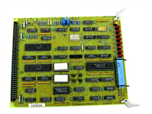
Revision Verification: The 531X133PRUAFG1 has a specific firmware checksum and a visible “F” in the suffix. Request the supplier to provide a high-resolution photo of the board’s label, a firmware version readout, and a test report showing the revision string. Beware of sellers who list PRUAAG1, PRUABG1, or PRUACG1 as PRUAFG1—the components, firmware, and features differ significantly.
-
Capacitor Condition: Inspect the 531X133PRUAFG1 for bulging or leaking electrolytic capacitors, particularly the 470µF, 1000µF, 2200µF, and 3300µF units near the power input section. Even with the upgraded 105°C rating, age and heat are the primary failure modes. The ultra-low ESR capacitors on the 531X133PRUAFG1 are expensive to replace, so ensure they are in good condition.
-
Potentiometer Integrity: The 12 trim-pots on the 531X133PRUAFG1 are precision 25-turn sealed units. Verify that they rotate smoothly without dead spots or excessive looseness; seized or jumpy pots indicate moisture ingress or thermal damage. The “current loop stability” pot is particularly sensitive—it must move freely to allow proper tuning.
-
Fieldbus Header Condition: If you plan to use the fieldbus gateway capability, inspect the 10-pin header on the 531X133PRUAFG1 for bent or corroded pins. This header is often overlooked during refurbishment, but damaged pins can prevent gateway module communication.
-
Test Documentation: Demand a functional test certificate that includes:
-
Analog input linearity (error < 0.1% of full scale) at 25°C, 45°C, and 60°C
-
Analog output accuracy (error < 0.15% of full scale) with slew-rate and clamping verification
-
Digital I/O loopback test
-
Tachometer input sensitivity test (down to 3V p-p)
-
Auto-tuning function verification
-
48-hour burn-in at 60°C with monitored current loop stability
-
Thermal derating verification (clock reduction at >60°C)
-
-
Warranty: Only purchase from suppliers offering a minimum 2-year warranty on the 531X133PRUAFG1, with a clear return policy if the board fails to initialize or exhibits any performance deviation. Given the scarcity and high value of this revision, extended warranties (3–5 years) are preferable.
-
Anti-Static Handling: The 531X133PRUAFG1 contains highly sensitive CMOS devices and precision analog components. Always store and ship in anti-static bags with proper ESD labeling. Upon receipt, inspect the bag integrity before opening. Do not handle the board without a grounded wrist strap.
Installation & Operational Precautions
-
Power Bus Discharge: Before inserting or removing the 531X133PRUAFG1, ensure the DC bus capacitors are fully discharged. Use a voltmeter to confirm less than 5V on the main DC terminals—this may take up to 10 minutes after power-off. Failure to do so can destroy the board’s power regulation circuitry and the sensitive ASIC.
-
ESD Protocol: Wear a grounded wrist strap and work on an ESD-safe mat. The 531X133PRUAFG1‘s edge connector, component leads, and the 10-pin fieldbus header are particularly susceptible; even a 15V static discharge can degrade the ASIC’s input protection.
-
Cable Separation: Maintain at least 300 mm (12 inches) between analog feedback cables (tachometer, encoder) and AC power/armature cables. The 531X133PRUAFG1‘s superior filtering is effective, but physical separation remains the best noise countermeasure—particularly critical for the sensitive 3V tachometer input.
-
Potentiometer Recording: Prior to removing an old board, use a multimeter to record the resistance value of each of the 12 trim-pots (measure between wiper and each end). Transfer these settings to the new 531X133PRUAFG1 as a starting point. Note that the “current loop stability” pot on the 531X133PRUAFG1 has no equivalent on earlier boards—you will need to tune it from scratch using the GE DC300 service manual procedure.
-
Auto-Tuning Procedure: To activate the auto-tuning feature on the 531X133PRUAFG1, apply a specific digital input sequence (consult the GE DC300 service manual for the exact sequence). During auto-tuning, the 531X133PRUAFG1 will momentarily excite the motor at reduced voltage—ensure the motor is uncoupled from the load to prevent mechanical damage.
-
Tachometer Damping & Current Loop Tuning: On the 531X133PRUAFG1, the “tachometer damping” pot should be set based on cable length: for cables under 30 meters, set to minimum; for 30–60 meters, set to midpoint; for over 60 meters, set to maximum. The “current loop stability” pot should be tuned by observing the armature current waveform on an oscilloscope—adjust for critical damping (no overshoot on step response). Fine-tune both settings during actual production runs.
-
Output Clamp Adjustment: The 531X133PRUAFG1‘s output clamp is set via a dedicated adjustment procedure. Do not set the clamp below 80% of the maximum firing command, as this may prevent the drive from delivering full torque during peak load conditions.
-
Firmware Lock: Do not attempt to reprogram or alter the firmware on the 531X133PRUAFG1. The microcontroller is factory-locked with a proprietary GE bootloader; any unauthorized write attempt will permanently brick the board.
-
Environmental Control: Ensure the cabinet’s ambient temperature does not exceed 60°C at the 531X133PRUAFG1‘s location. If necessary, add a spot cooler or redirect airflow to prevent thermal derating (clock reduction) which reduces performance. The thermal derating is a safety feature, not a substitute for proper cooling.
-
Gateway Module Installation: If installing a fieldbus gateway module on the 531X133PRUAFG1, ensure the module is powered off before connection. The 10-pin header is not hot-swappable; connecting or disconnecting a gateway module with power applied can damage both the module and the 531X133PRUAFG1.
-
Regular Inspection: Given the value and scarcity of the 531X133PRUAFG1, schedule regular visual inspections (every 6 months) to check for capacitor bulging, discoloration, or any signs of overheating. Clean the board gently with compressed air to remove dust buildup, which can insulate components and accelerate thermal degradation.
A-B 1404-M405A-DNT
ABB AO810
SCHNEIDER 140NOE77101
.jpg)


Reviews
There are no reviews yet.