
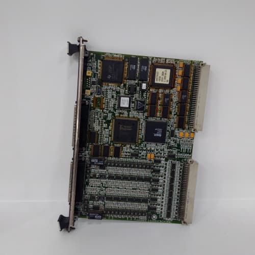
Description
Technical Specifications
| Parameter | Specification |
|---|---|
| Manufacturer | General Electric |
| Model | IS200JPDBG2A |
| Pulse Inputs | 8–16 pulse inputs (J-type, speed, flow, position sensors) – expanded |
| Bridge Functions | Pulse data bridging, data routing, network translation (enhanced) |
| J-Type Gateway Functions | Data routing, protocol conversion, gateway communication |
| Supported Protocols | Modbus RTU, GE pulse protocols, DNP3, J-type protocols |
| Processing | Enhanced processor (“2” series) with larger buffer memory |
| Power | +5V DC / 2.5A, ±15V DC / 0.5A |
| Temp Range | -30°C to +65°C |
| MTBF | > 105,000 hours |
| Revision Note | “2” series = enhanced processing; “A” suffix = specific configuration |
Advantages and Key Features
Enhanced Processing Power: The “2” series IS200JPDBG2A provides faster data processing, larger buffer memory, and expanded channel capacity compared to “1” series boards.
Expanded Channel Capacity: Handles 8–16 pulse inputs, doubling the capacity of “1” series boards.
Expanded Protocol Support: Includes DNP3 for enhanced network integration.
Enhanced Bridging Features: Improved pulse data routing and network translation.
Application Fields and Case Studies
Used in demanding pulse data bridging applications requiring enhanced processing, expanded channel capacity, or expanded protocol support. In a large 800 MW plant, the IS200JPDBG2A provided enhanced pulse bridging with expanded channel capacity.
Comparison with Competing Products
| Dimension | IS200JPDBG2A | IS200JPDBG1ABB | IS200JPDBG1A |
|---|---|---|---|
| Series | 2 (Enhanced) | 1 (Standard) | 1 (Standard) |
| Pulse Inputs | 8–16 | 4–8 | 4–8 |
| Processing Power | Higher | Standard | Standard |
| Protocol Support | + DNP3 | Specialized | Standard |
| Power Draw | 2.5A | 2.0A | 2.0A |
Selection Recommendations
Choose IS200JPDBG2A for demanding pulse bridging applications requiring enhanced processing, expanded channel capacity, or expanded protocol support. Select over “1” series boards when higher performance or more channels are needed. Confirm rack power supply capacity for the “2” series board. Verify compatibility with your pulse sensors and bridging requirements.
Precautions and Important Notes
Use ESD-safe handling. Verify field wiring and pulse connections. The IS200JPDBG2A draws 2.5A (+5V) – verify rack power supply capacity before installation. Confirm compatibility with your specific pulse sensors and bridging requirements. Never interrupt firmware updates. Document all configurations. Store spares in anti-static packaging. Do not mix IS200JPDBG2A with “1” series boards in redundant pairs without verifying identical firmware. Allow 30 seconds boot time. Test all bridging and gateway functions during commissioning. Ensure proper shielding for pulse signals. The IS200JPDBG2A is critical for pulse data bridging – ensure all settings are verified before placing in service. Consider power supply upgrades if multiple “2” series boards are installed. Regular verification of pulse data quality and bridging performance is recommended. Ensure communication cabling does not exceed maximum recommended length. The higher performance may require firmware updates to other system components. If replacing a “1” series board, verify all devices and configurations are compatible before installation.
Schneider 140NOE77101
A-B 1794-IE8XT
A-B 1769-OF4VI/A


Reviews
There are no reviews yet.