
")
")
Description
Product Introduction
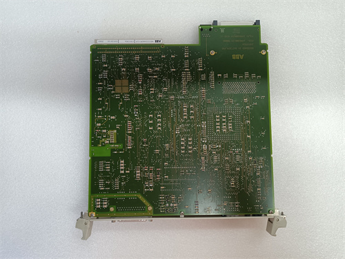
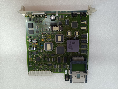
The ABB DO630 is a workhorse digital output module from the ubiquitous S800 I/O family, designed for use with ABB’s AC800M controllers in systems like 800xA. Simply put, it’s the “hand” of your automation system—it takes the low-voltage commands from the PLC’s logic and turns them into 24 V DC signals to actually switch things on or off. You connect it to terminal units like TU810 or TU830, and it handles the rest. The clever bit about the DO630 is that it uses solid-state transistor outputs. This means it’s incredibly fast and has a virtually unlimited mechanical lifespan compared to old-school relays. It also packs 16 channels into a single, compact module, saving valuable space in your cabinet. Each channel is protected against short circuits, and there’s group error reporting, so you know immediately if something goes wrong in the field. I’ve seen these modules running for decades on oil platforms and in chemical plants without a single hiccup—they’re built to last.
Key Technical Specifications
| Parameter | Value |
|—|—|—|—|
| Model | ABB DO630 |
| Type | Digital Output Module |
| Channels | 16 |
| Output Type | Transistor (PNP), short-circuit protected |
| Nominal Voltage | 24 V DC (from external source) |
| Output Current | 0.5 A per channel, max 2 A per group, 8 A total per module |
| Switching Frequency | Max. 100 Hz (resistive load) |
| Status Indication | 16 yellow LEDs for channel status, 1 green LED for module status |
| Isolation | Group isolation (8 channels per group) |
| Power Consumption | 20 mA + load current (from module bus) |
| Mounting | On S800 terminal unit (e.g., TU810, TU830, TU850) |
| Operating Temp | 0 to +55 °C |
SOP Quality Control
Every ABB DO630 we handle goes through a rigorous check before it’s shipped. We don’t trust stickers; we trust our test gear.
-
Incoming Inspection: First, we visually check the housing for cracks or damage. We verify the serial number against our records and make sure the gold-plated edge connector is pristine—no scratches or oxidation.
-
Live Functional Test: The module is installed in a live test rack with a genuine ABB AC800M controller and a TU830 terminal unit.
-
Power-up: We check the green module status LED comes on.
-
Channel Test: Using Control Builder software, we force each of the 16 channels ON and OFF. At the terminal unit, a calibrated Fluke 115 multimeter verifies the presence and absence of 24 V DC on each corresponding terminal.
-
Load Test: We connect a test load (a 24V relay coil) to a few channels to ensure they can handle the rated current and catch any flyback issues.
-
Diagnostics: We intentionally short-circuit a channel to verify the module’s built-in protection kicks in and the diagnostic LED reports correctly.
-
-
Electrical Test: We perform an insulation resistance test between the output groups and the backplane bus to ensure no leakage.
-
Burn-In: The module is left powered and cycling channels for 2-4 hours to ensure long-term stability.
-
Packing: After passing all tests, it’s sealed in an anti-static bag with a desiccant pack and packed securely for shipping. A test report is included.
Tech Pitfall Guide (Real-World Advice)
Here’s the stuff the manual doesn’t always scream loud enough. I’ve seen these mistakes cost people hours of troubleshooting.
-
Firmware Mismatch: The DO630 itself has minimal firmware, but the issue is with the configuration. Older versions of the module might not support some new diagnostic features in modern 800xA systems. *Real-world case: A plant installed an old DO630 module from stock, and the system couldn’t read its diagnostic data, causing a persistent “module communication error.” They had to update the module’s configuration in the project.*
-
DIP Switch / Jumper Errors: Unlike some modules, the DO630 doesn’t have many user-set jumpers, but the terminal unit it plugs into (like the TU830) often has jumpers for power distribution. Crucial tip: Photograph the jumpers on your old TU base before you touch anything. If you misplace a jumper on the TU, you could starve the DO630 of power or fail to distribute power to field devices.
-
Terminal Unit Incompatibility: The DO630 is designed for specific S800 terminal units. It’s physically keyed to fit, but you must ensure you’re using the correct model, like a TU810, TU830, or TU850. *Real-world case: Someone tried to force a DO630 onto an old TU800 series base from a different system. It didn’t fit, and they cracked the housing.*
-
Power Supply Starvation: The DO630 doesn’t create the 24 V for the loads; it just switches it. You must provide a robust external 24 V DC supply to the field terminals. *Real-world case: A startup engineer connected all 16 outputs to large relays but used a tiny power supply. When more than 4 relays pulled in, the voltage dropped, and the PLC logic failed.*
-
ESD (Electrostatic Discharge): The transistor outputs are sensitive. *Real-world case: A technician in a synthetic jacket touched the exposed terminals of a new DO630 right after pulling it from the bag. A spark jumped, and one of the output channels was dead on arrival.* Always, always use a grounded anti-static wrist strap.
Installation & Configuration Guide
Swapping a DO630 is straightforward if you follow the steps.
Phase 1 – Preparation (~5 min)
-
Safety: Isolate the power to the S800 rack. Turn off the external 24 V supply for the field circuits.
-
Tools: Get your anti-static wrist strap, a Fluke 115 multimeter, and a small flathead or PH1 screwdriver.
-
Backup: In Control Builder, perform a “Save As” to back up your entire project. It takes 2 minutes and saves hours.
-
Documentation: Find the terminal unit (e.g., TU830) that your DO630 is mounted on. Take a clear photo of the wiring on the terminal block. ⚠️ You will thank yourself later.
Phase 2 – Removal (~3 min)
-
Marking: The wiring is on the base unit, not the module. You don’t need to remove wires if you’re just swapping the DO630.
-
Extraction: Press the locking clip at the top and bottom of the module’s faceplate. Grip the module firmly and pull it straight out from the terminal unit. Pull evenly; don’t wiggle it side-to-side as this can stress the backplane connector.
Phase 3 – Installation (~3 min)
-
ESD: Unpack the new ABB DO630 only after grounding yourself.
-
Verify: Check that the new module’s part number is exactly DO630.
-
Insertion: Align the module with the guides on the terminal unit. Push it in smoothly and firmly until you hear a distinct “click” from both the top and bottom locking clips. A flush fit means a good connection.
-
Wiring: You do not need to touch the field wiring on the base unit. It’s already correct.
Phase 4 – Power-On & Test (~10 min)
-
Power On: Restore power to the S800 rack and the external 24 V field supply.
-
Check LEDs: Look at the module’s front. The green “Module Status” LED should be steady. Now, for fun, manually activate a channel.
-
The Test:
-
Go to your engineering station and open Control Builder.
-
Find the DO630 in your project tree and go to its diagnostic view.
-
Use the “Force” function (or a test script) to turn Channel 1 ON.
-
Walk to the rack and verify that the yellow LED for Channel 1 on the DO630 lights up. Use your multimeter to check for 24 V DC at the corresponding terminal on the base unit.
-
Repeat for a couple more channels to be safe.
-
-
Final Check: Run the system for 30 minutes and monitor for any channel faults.
Frequently Asked Questions (FAQ)
Q: Does the ABB DO630 support hot-swap (hot swapping)?
A: No. The S800 I/O system is not designed for hot-swapping output modules. You must disconnect the power to the rack before removing or inserting a DO630. Attempting to do it live can cause a short circuit on the backplane, potentially damaging the module, the terminal unit, and even the rack’s power supply.
Q: Is the DO630 still in production or is it obsolete?
A: While the core S800 I/O series is still an active and supported product line for ABB, some specific part numbers are updated. The DO630 is widely available as a standard spare part. We keep it in stock as a new original (New Surplus) unit.
Q: What’s the difference between the DO630 and a module like the DO610?
A: The main difference is channel count and current. The DO630 is a high-density module with 16 channels at 0.5A each. The DO610, for example, typically has fewer channels (e.g., 8) but often a higher current rating per channel. Choose based on your cabinet density and the current requirements of your field devices.
Q: Will I lose my program if I replace the DO630?
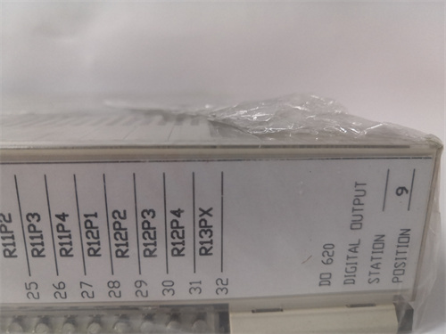
ABB-WT98 PLC
8500-ANIO PLC
PCI4000
PCIE-6351 PLC
CP40B-PO961BC PLC
5KH39QNA002BX PLC


Reviews
There are no reviews yet.